Download
1 / 40
400 likes | 479 Views
Lecture 2-Building a Detector. George K. Parks Space Sciences Laboratory UC Berkeley, Berkeley, CA. Brief summary of Lecture 1. Operations of Detectors: • Detection of particles and photons relies how particles and photons interact with matter.

E N D
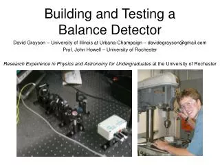
Lecture 2-Building a Detector George K. Parks Space Sciences Laboratory UC Berkeley, Berkeley, CA
Brief summary of Lecture 1 Operations of Detectors: • Detection of particles and photons relies how particles and photons interact with matter. • Charged particles lose energy by ionization and radiation. - The formula dE/dx gives information on stopping power, that in turn allows us to choose the type of detectors and how thick the detector should be, for example. • Photons interact with matter by Photoelectric, Compton and Pair processes. - These processes produce electrons and they interact by ionization. - These processes have energy dependence, for example, allowing us to focus on maximizing photoelectric and minimizing Compton processes.
Brief summary of Lecture 1 (cont’d) • A detector is a device that converts incident particles and photons into signals without distorting the original information. • Two major physics discoveries led to important development of detectors: photoelectric effect and that secondary electrons can be produced. • Detector components include Photomultiplier Tubes (PMT) and Channel Electron Multipliers (CEM). - PMTs multiply the number of electrons by discreet dynodes whereas CEMs multiply electrons continuously. • Assemble a million of CEMs in a geometrical array and form Micro Channel Plates (MCP). - Each channel is a pixel, so MCPs can form Images.
Schematic of Earth’s Magnetosphere • Assignment: • Design a detector to measure particle or photon fluxes from space.
Measurement Requirements • Particles in space have energies <1 eV to > 1021eV. • Fluxes vary 18 orders of magnitude, as in Oxygen. • In the Vicinity of Earth, - Ions have flux range of 7 orders of magnitude - Electrons have flux range ~4 orders of magnitude • One detector CANNOT measure all of these particles!
Requirements • Science requirements • What science are we studying? • What’s new and why is this science important? • eg, in ring current studies, what new science for neutral imagers? (2) Measurement requirements • What measurements are required to accomplish the science goals? • What is known about these measurements? (3) Instrument requirements • What kind of instrument needed to obtain the measurements sought? • Have such instrument been built before? (4) Mission Requirements, Constraints, etc… • FOV, Weight, Volume, Power, etc… • Optimize the instrument to yield the best data for achieving the science goals.
Detectors and Components Detector Components Material • PMTs electron multipliers (photocathodes) • Channeltrons coated glass; continuous multipliers • Funneltronschanneltron with wide funnels • MCPs multiple channeltrons• Geiger/proportional • Solid State Detectors Semi-conductors • Ion Chambers Gas filled • Proportional counters Gass filled • Cerenkov detectors Chunk of glass + pm tube • Photodiodes Semi-conductors • Cerenkov Transparent Material (Glass) + PMTs • ScintillatorsMaterial for photons or particles to interact.
Detectors for Space • Space Detector is one of a kind instrument! • Instrument are designed for a specific science goal • Detector designed to measure fluxes and energies in specific energy range. • All detector systems have large amount of complex details. • Knowing the details of the detectors can help to understand what they measure, their limitations and capabilities. • Also, they can help to relate the measured quantities to the original propertiesof the photon source.
Measurement and Instrument Requirements • Basically, Space borne detectors measure Total energy or Energy per Charge of the particles. • X- and g-rays (~keV – 10’s MeV; Auroral and Solar) Scintillators + PMTs (Total energy) Solid State Detectors (Total Energy) • Particles (A few eV to ~35 keV/q; Magnetospheric and Solar) - Electrostatic analyzers (Energy/q) Low end limited by SC potential High end limited by HV • Particles ( ~20 keV - hundreds MeV; Magnetospheric, Solar, Cosmic rays) - Solid State Detectors (Total Energy) Low end limited by dead layer High end limited by number of detectors stacked • New thin Dead Layer SSD: >2 keVe- and ~6 keV for p+ (CINEMA)
A Simple Detector for Photon Measurement • Science Requirements: Measure Energy Spectra from Aurora. • PMT + Scintillator + Electronics = Complete Detector System! • Old but very reliable technique for detecting photons. Scintillation detectors still used in particle and nuclear physics, solar physics, space physics, astrophysics, health physics, oil exploration, baggage scanning, etc..
Imaging Detector Collimator • Photon goes through a Pin hole, Coded aperture, Modulation Collimator (RHESSI) • Incident photon stops in the scintillator. • Scintillation photons propagate to one or several of the PMTs • From ratios of counts, one can determine the direction of arrival of the photon.
Scintillators • Scintillators are materials that can scintillate (emit light). • A charged particle or photon traversing a scintillator excites (ionizes) electrons and light is emitted in the de-excitation process. • Amount of light proportional to incident energy of photon. • Scintillators can be liquid, solid or gases, organic or inorganic material. • Organic crystals: aromatic hydrocarbon compounds • Organic liquids: organic scintillators dissolved in organic solvents, benzene, xylene, toluene, etc.. (not practical for space) • Plastic: organic scintillators polymerized to form solids. Plastic can be shaped and machined to form any shape desired. Inexpensive. Very nice! • Gaseous scintillators: Nitrogen and noble gases, He, Ar, Kr, Xe. • Inorganic Crystals: Alkali metal halides dopedwith a small amount of impurity activators.
Common Inorganic Scintillators Alkali halide Scintillators: • NaI(Tl), CsI(Tl), CsI(Na), CsI(pure), CsF, KI(Tl), LiI(Eu), Non-alkali Scintillators: • BaF2, CaF2(Eu), ZnS(Ag), CaWO4, CdWO4, YAG(Ce), BGO, etc… Newly developed scintillators: • LaCl3(Ce) and LaBr3(Ce) • What kind of scintillator to use depends on the type of experiment - Gas scintillator: Fission fragments and heavy charged particles. - Liquid scintillators: neutrinos - Inorganic NaI(Tl): X- and g-rays and particles. - Inorganic BaF2: neutrons (Note: Scintillators respond to both charged particles and photons)
Light transmission • Scintillators must be able to transmit the light it generates. • Generally not a problem with most scintillators.
CsI Scintillator • Light emission wavelength depends on the “doping” compound. • Light emission efficiency sensitive to temperature
Emission Spectrum of scintillators • Scintillators produce different amount of light. • NaI (Tl) more efficient than CsI (Na) • It’s better if there is more light. • Why? Directly affects the energy resolution of the detection system. • How? Affects Statistics.
Absorption in material • X-and gamma rays are penetrating. • Need high Z material to stop them. • Inorganic scintillators have higher density that organic scintillators. NaI(Tl) • Io = # incident • = # hnthrough x • x = thickness • m = attenuation coefficient
Temperature Dependence of NaI(Tl) • NaI (Tl) Scintillator is temperature sensitive. • Worrisome! Temperature in space can change. • Temperature variations impact measurements. - Lose efficiency, affect pulse height. • Need in flight calibration.
Entrance Window Material • NaI(Tl) is hydroscopic, sealed in vacuum. • Transmission of X-rays through various material in front of sealed NaI (Tl).
X-ray Absorption in NaI(Tl) • Density = 3.67 g/cm3 • % of incident X-rays stopped in NaI(Tl) • Dip ~33 keV, K-absorption edge. • 2 mm 70% @ 100 keV • 1/4 in (6.35 mm) ~95% @ 100 keV
X-ray Absorption in CsI(Tl) • Density = 4.51 g/cm3 • 2 mm 83% @ 100 keV • ¼ in (6.35 mm) ~100% at 100 keV
X-ray Absorption in BGO •Density = 7.13 g/cm3 • % of incident X-rays stopped in BGO. • 1 mm 95% @ 100 keV • 1.5 mm ~100% @ 100 keV
X-ray Absorption in Plastic • Density = 1.03 g/cm3 • Plastic scintillator often used in anti-conincidence part of an experiment to reduce cosmic ray contribution. • 10 mm 20% @ 20 keV • 130 mm 82% @ 100 keV 98% @ 20 keV
Properties of Scintillators (Room T) rnetlComments NaI (Tl) 3.67 1.85 38 0.25 ms 415 hydroscopic CsI (Tl) 4.51 1.80 65 0.68 550 slightly CsI(Na) 4.51 1.84 39 0.46 420 slightly LaBr3(Ce) 5.08 5.47 63 16 356, 387 hydroscopic BGO 7.13 2.15 8 0.30 480 No Plastic 1.03 1.58 10 0.002 423 No • For NaI(Tl), 1 keV incident X-ray yields 38 photons. • This is about 26 eV/photon. • The peak photon wavelength is ~4 eV. • 4x38=142 eV. Conversion Efficiency ~7%.
Maximize photon collection • Scintillation emitted in all directions. Optics is very important! - Optical self-absorption Usually not a problem - Loss at surfaces inside the scintillatorhousing for NaI (Tl) Paint surfaces with highly reflecting paint (MgO) diffuse or specular reflection? - Internal trapping of light - Coupling to PMTs Match index of refraction Silicone for normal use If Temperature varies, use hard epoxy • Direct coupling best. But sometimes not possible. - Light pipes to PMTs. Lose photons (affects energy resolution).
Plastic Scintillator (NE 102) • Light emission by various particles • Sufficient for A/C application • Range of various particles • Few mm to stop 2 MeV p+
Light emission of Inorganic Scintillators • Light emission spectra of scintillators. • Matching scintillator emission spectra with photocathode spectral response • Quantum efficiency of Bialkali photo-cathodeof PMT
Desired Properties of Scintillators • Density should be high enough for good stopping power. • Convert photons into detectable light withhigh efficiency. • Conversion should be linear. The light yield should be proportional to the deposited energy over a wide range of energy as possible. • The scintillator should be transparent to the wavelength of its own emission. • Fast rise time (for timing application). • The decay time of the induced luminescence should be short so that fast signal pulses can be generated. • The material should be of good optical quality and can be produced in sizes large enough for a practical detector. • Change slowly with temperature. • Minimum afterglow. • The index of refraction should be near that of glass (~1.5) to permit efficient coupling of the scintillator light to a PMT or other light sensors.
Conversion Efficiency Calculation (cont’d) • All photons absorbed in the scintillator by photoelectric process. • Desire ~100% of photons stopped. • ½ inch scintillator (NaI(Tl) absorbs most of X-rays with hn <100 keV. • But Conversion efficiency is <10%!
More Worries! • Photon Interaction in Scintillators are Probabilistic! • Detector Efficiency (DE) relates the amount of incident radiation to the amount measured in the detector. • DE estimates the Counting rate expected in a detector. • Calibration source strength must be known. For a known radioactive source, DE = D/N D = Number of Photon counts in the detector N = Number of photons Emitted by source
Conversion Efficiency Calculation • To compute DE for different energies, use different radioactive sources. • Half-life of Sources. How to correct? where A = activity level now Ao = original activity level t = time interval since the source calibrated t = mean half-life of the source 1 Curie = 3.7x10¹⁰ dps
Summary of important factors • Material and Thickness of entrance window of scintillator (Be, Al, etc). Should be sealed for vacuum operation. • Material of exit window of scintillator (quartz, glass, plastic, etc..) • Size, shape and thickness of scintillator (round, hexagonal, square) • Entrance window of PMT (quartz, boronsilicate, ..) • How to couplescintillator to PMT (hard, soft, nothing)
Reminder-A simple Photon Detector • Discussed Scintillator • Need to understand how the PMT works.
Reminder-Photomultiplier Tube • • PMT a device to multiply number of electrons • hn incident on input window • e- emitted at photocathode • Accelerate e- to first dynode • Emits secondary e- • Multiply secondary e- - Collect ~106e- at anode
PMTs Operating principle of PMTs
Photomultiplier tubes (PMTs) • Hamamatsu lists more than 300 different types of PMTs. • Different shapes, size, gain, etc.. • So many different parameters! • What do they mean? • How does one choose which PMTs to use?
Reminder-Buiding Detectors Goals are for detectors to have good energy resolution, low noiseand high detector efficiency, good signal to noise ratio. • In X- and g-ray astronomy, energy resolution is important for separation of peaks close to each other. • Require Low noise because the source may be weak. • High detector efficiency because not every X-ray that pass through the detector will produce a count. • Want high probability that an X- ray entering a detector will interact and produce a count. • Information on how detectors work come from nuclear, solid state, atomic, quantum and plasma physics!