Download
1 / 31
310 likes | 408 Views
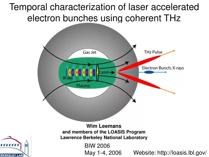
Temporal characterization of laser accelerated electron bunches using coherent THz. Wim Leemans and members of the LOASIS Program Lawrence Berkeley National Laboratory. BIW 2006 May 1-4, 2006. Website: http://loasis.lbl.gov/. plasma. d=2 mm. LWFA: two regimes for bunch production

E N D
Temporal characterization of laser accelerated electron bunches using coherent THz Wim Leemansand members of the LOASIS ProgramLawrence Berkeley National Laboratory BIW 2006 May 1-4, 2006 Website: http://loasis.lbl.gov/
plasma d=2 mm • LWFA: two regimes for bunch production • Large-energy-spread bunch (unchanneled) • Quasi-mono-energetic bunch (channeled) Laser wakefield acceleration Ionization of gas by laser Ponderomotive push of plasma electrons Restoring force from due to charge separation Density oscillation: strong electric fields (100 GV/m) Sprangle et al. (92); Antonsen, Mora (92); Andreev et al. (92); Esarey et al. (94); Mori et al. (94)
Tool: LOASIS multi-terawatt laser 100 TW-class Ti:sapphire Shielded target room 10 TW Ti:sapphire LOASIS laser system Three main amplifiers (Ti:sapphire,10 Hz): - Godzilla: 0.5-0.6 J in 40-50 fs (10-15 TW) ===> main drive beam (to date) - Chihuahua: 20-50 mJ in 50 fs ===> ignitor beam 250-300 mJ in 200-300 ps ===> heater beam 100-200 mJ in 50 fs ===> colliding beam - T-REX: 2-3 J in 30-40 fs ===> capillary experiments } guiding
CCD Phosphor Phosphor vacuum Magnet Laser beam Gas Jet e-beam on phosphor screen Electron beam e-beam spectrum Jet Energy spectrum obtained with a magnetic spectrometer Charge Detector ~10 mrad Magnet OAP Mid 90’s -2003: short pulse laser systems generate electron beams with 100 % energy spread LWFA experiments produce electrons with: 1-100 MeV, multi-nC, ~100 fs, ~10 mrad divergence Modena et al. (95); Nakajima et al. (95); Umstadter et al. (96); Ting et al. (97); Gahn et al. (99); Leemans et al. (01); Malka et al. (01)
Dominates if sz < l How short are the bunches ? Simulations predict 10-20 fs Can we measure them? (Is the linac stable enough?) Coherent emission
Diagnostic relies on coherent transition radiation from the plasma-vacuum boundary Laser-Wakefield Accelerator Schematic for Transition Radiation Leemans et al., Phys. Rev. Lett. (2003); Schroeder et al., Phys. Rev. E (2004); Van Tilborg et al., Phys. Rev. Lett. (2006) Diagnostic implementation: • Use radiated field • Couple out of vacuum chamber Boundary size
CTR (THz) in spectral and temporal domain Diffraction function (boundary size ) • Intense THz source • 0.01-10 MV/cm at focus (up to 10’s of J in THz pulse) • ‘traditional’ laser-based sources deliver <100 kV/cm Form factor Single electron TR CTR spectrum CTR in time Schroeder et al., Phys. Rev. E (04) van Tilborg et al., Laser Part. Beams (04) van Tilborg et al., Phys. Plasmas, submitted
Temporal THz measurement: electro-optic sampling Valdmanis (82); Yariv (88); Gallot (99); Yan (00); Fitch(01); Wilke(02); Berden(04); Cavalieri(05) Phase shift is proportional to THz field
Electro-Optic measurement of Coherent Transition Radiation yields information on laser accelerated electron beam: < 50 fs bunches W.P. Leemans et al., PRL2003 C.B. Schroeder et al., PRE2004 J. Van Tilborg et al., Laser and Particle Beams 2004; PRL 2006
Choice of EO-material affects temporal resolution • CTR based on 50 fs (rms) Gaussian electron bunch • ZnTe vs GaP: • ZnTe cutoff ~ 4 THz • GaP cutoff ~ 8 THz
Scanning technique provides bunch duration: Resolution limited by crystal properties Scanning technique (takes 1.5 hours) • < 50 fs bunches • Synchronization • Charge and bunch stability Van Tilborg et al., PRL2006, Phys. Plasmas06
Single-Shot Technique for EO detection of THz pulses: Information on every bunch 3 ps 50 fs • < 50 fs bunches • peak E-field of ECTR≈150 kV/cm J. van Tilborg et al., submitted to PRL G. Berden et al., Phys. Rev. Lett. 93, 114802 (2004)
Shot A Spectrum A Shot B Spectrum B Experiments show double THz pulse Red curves are double-THz-pulse-based waveforms and spectra • Use GaP instead of ZnTe • Higher bandwidth • Observation • Temporal waveform: double pulse • Spectral modulation • Why? • Double bunch e-beam ?
Single-shot 2D EO imaging provides spatial profile of THz beam Shot 1 =546 fs 5 mm Shot 2 =796 fs Shot 3 =1154 fs 7 mm • Measure 2 D THz profile • Focused THz beam • Collimated laser beam • Step laser beam in time Van Tilborg et al., to be published
‘Ray Optics’ approach to analyze spatio-temporal effects of coma Shot 3 =1154 fs
with coma t=0 t=-0.3 t=+0.3 t=-0.6 t=+0.6 Propagation of a single-cycle pulse through focus no coma t=0 t=-0.3 t=+0.3 t=-0.6 t=+0.6
No coma With coma ‘Ray optics’ model for waveform and spectrum
2004 Results: High-Quality Bunches • Large spot size, no channel (ZR order of gas jet length) • RAL/IC: (Mangles et al.) • No Channel: 21019 cm-3 • Laser: 12 TW, 40 fs, 0.5 J, 2.51018 W/cm2, 25 m • E-bunch: 1.4108 (22 pC), 70 MeV, E/E=3%, 87 mrad • LOA: (Faure et al.) • No Channel: 0.5-2x1019 cm-3 • Laser: 30 TW, 30 fs, 1 J, 18 m • E-bunch: 3109 (0.5 nC), 170 MeV, E/E=24%,10 mrad • Controlled laser guiding with channel • LBNL: (Geddes et al.) • Plasma Channel: 1-4x1019 cm-3 • Laser: 8-9 TW, 8.5 m, 55 fs • E-bunch: 2109 (0.3 nC), 86 MeV, E/E=1-2%, 3 mrad
2w probe Cylindrical Mirror Main beam <500mJ >50fs Pre ionizing Beam 20mJ H, He gas jet e- Heater beam 100mJ 250ps Interferometer CCD & Spectrometer Plasma Channel Production: Hydrodynamic Ignitor-Heater in H2 Gas Jet Plasma channel Ti:sapphire * P. Volfbeyn, E. Esarey and W.P. Leemans, Phys. Plasmas 1999 C.G.R. Geddes et al., Nature 431, p. 543 (2004), Phys.Rev.Lett. (2005).
At laser power of 8-9 TW: e-beam with %-level energy spread, 0.3 nC, 1-2 mm-mrad Beam profile Spectrum Unguided Guided 2-5 mrad divergence Charge~100 pC C.G.R. Geddes et al., Nature 431 (2004); PRL (2005); Phys. Plasmas 2005
Group velocity of laser < speed of light causes particle dephasing which causes momentum bunching gv Momentum z-vgt Phase • Dephasing distance: • Control via density and a0 (laser intensity) • Optimum acceleration requires Lacc = Ldeph: channel or large ZR
Wake Evolution and Dephasing Yield Low Energy Spread Beams in PIC Simulations 200 WAKE FORMING Longitudinal Momentum 0 Propagation Distance 200 INJECTION Longitudinal Momentum 0 Propagation Distance 200 DEPHASING DEPHASING Longitudinal Momentum 0 Propagation Distance Geddes et al., Nature (2004) & Phys. Plasmas (2005)
1-2 GeV e- beam Next step: GeV laser driven accelerator Capillary L'OASIS 100 TW laser • Lower density needed: capillary discharges Increasing beam energy: cm-scale capillary discharge + 100 TW laser Capillary TREX Laser Plasma injector 40-100 TW 40 fs 3-5 cm
Hydrogen based capillary discharge produces suitable density profile for guiding • Mach-Zehnder interferometer CCD • 209 m diameter capillary • 85 mbar initial pressure • n0 = 8.5x1017 cm-3 • 32 micron matched spot A. Gonsalves et al., submitted to PRL
Input Output 40 TW power guided over > 3 cm P = 0.1-40 TW in 40 fs, 10 Hz wx,in=wy,in= 26 m wx,out=wy,out= 33 m
LOASIS GeV Spectrometer Forward view: 0.16 - 1GeV moderate resolution - Maximum resolving energy: ~1.1 GeV Yoke - Large momentum acceptance (factor 25) Pole - High resolution (bottom: <1%, forward: 2~4%) Chamber Interaction point Capillary Beamline 1GeV Mirror and cameras Phosphor 40MeV Bottom view: 40-160 MeV high resolution(under const.) 160MeV Chamber Shielded mirror and cameras
Up to 1 GeV achieved with 40 TW laser pulses 25 TW E<0.6 GeV Q~50-300 pC DATA UNDER PRESS EMBARGO 40 TW E< 1.1 GeV Q~50-100 pC
Summary • Single shot EO-based methods of CTR THz radiation measures < 50fs laser-wakefield accelerated e-bunches • Single cycle THz detected, 0.4 MV/cm • Spatio-temporal coupling from aberrations in imaging can lead to apparent double bunches • GeV electron beam generated in 3.3 cm with 40 TW laser pulses • THz based bunch profile measurements underway • Novel diagnostics needed with fs and sub-fs resolution for slice energy spread and emittance • Next steps are on staging modules towards 10 GeV
Scientists and Techs of LOASIS team Staff: Exp’t: C. Geddes, W. Leemans, C. Toth Theory: E. Esarey, C. Schroeder, B. Shadwick, Postdocs:E. Michel*, P. Michel, B. Nagler Students: K. Nakamura, J. van Tilborg, G. Plateau,T. Wolf Techs: D. Syversrud, N. Ybarrolaza Collaborators: D. Bruhwiler, D. Dimitrov, J. Cary--TechX Corp T. Cowan, H. Ruhl -- University of Nevada, Reno* S. Hooker, A. Gonsalves--Oxford University, UK R. Ryne, J. Qiang--AMAC, LBNL R. Huber, R.Kaindl, J. Byrd, M. Martin--LBNL W. Mori--UCLA D. Jaroszynski-University of Strathclyde, UK M. Van der Wiel-TUE, Eindhoven, NL G. Dugan--Cornell University D. Schneider, B. Stuart, C. Barty, C. Bibeau--LLNL