Download
1 / 18
190 likes | 334 Views
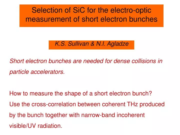
Selection of SiC for the electro-optic measurement of short electron bunches. K.S. Sullivan & N.I. Agladze. Short electron bunches are needed for dense collisions in particle accelerators. How to measure the shape of a short electron bunch?

E N D
Selection of SiC for the electro-optic measurement of short electron bunches K.S. Sullivan & N.I. Agladze Short electron bunches are needed for dense collisions in particle accelerators. How to measure the shape of a short electron bunch? Use the cross-correlation between coherent THz produced by the bunch together with narrow-band incoherent visible/UV radiation.
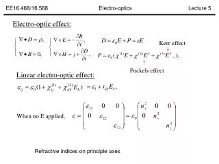
Electro-optic crystals • Material-specific properties • Electro-optic effect on polarized light http://dev.fiber-sensors.com/wp-content/uploads/2010/08/electro-optic_example-01.png
Cross-correlation of coherent and incoherent radiation in EO medium THz coherent pulse Incoherent pulse • Cross-correlation • Non-collinear propagation enables a delay dependence CRYSTAL Advantages Single shot capability Resolution determined by the EO crystal dispersion DETECTOR
Zinc Telluride (ZnTe) • High electro-optic coefficient • Useful frequency range limited by low vibrational mode (190 cm-1 compared to GaP’s 366 or SiC’s 794) • Dispersion due to TO resonance http://refractiveindex.info/figures/figures_RI/n_CRYSTALS_ZnTe_HO.png
Silicon Carbide (SiC) • Comparable electro-optic coefficient to ZnTe • Higher TO resonance permits larger frequency range
Polytype Choice Cubic SiC Hexagonal SiC • Pure • Expensive • Subject to free carriers • Readily available http://japantechniche.com/wp-content/uploads/2009/12/sdk-sic-mosfet.jpg
6H Considerations • Free carriers or doping • Metallic behavior • Electro-optic coefficient’s angular dependence http://metallurgyfordummies.com/wp-content/uploads/2011/04/doping-semiconductor.jpg
6H Transmission • Increase in transmission toward Brewster angle • Lacks metallic free carriers • Unexpected feature at ~110 wavenumbers
6H Absorption Coefficient • Use transmission relation to plot absorption coefficient, α • Ideally zero • Notable frequency dependence • Unknown feature possibly due to fold-back or material defects
Focus on 3C • Unlike 6H, 3C does not require calculation of an angle to maximize the electro-optic coefficient • Cubic/Zinc-blende structure similar to ZnTe and GaP • Necessary to calculate electro-optic response http://upload.wikimedia.org/wikipedia/commons/4/4f/SiC3Cstructure.jpg
Electro-optic Response • Transmission coefficient based on refractive index • Integral uses frequency, thickness, phase velocity of THz radiation, and group velocity at optical frequency • Shape of resulting function comes primarily from the mismatch between phase and group velocity
Dielectric Model Because of the electro-optic response function’s reliance on phase and group velocities, we need a model of the dielectric function from the UV to the THz.
Comparative Responses • GaP shown at optical group velocity at 8352 cm-1 • ZnTe at 12500 cm-1 • SiC at 37495 cm-1 • Cut-off frequency set at 4 THz
Electro-optic Performance • Previous approach masks full electro-optic properties • Transmission, crystal thickness, and electro-optic coefficient all important • Figure of merit proportional to the polarization rotation produced by the THz field
Alternate Comparison • Material group velocity maintained by choosing the optimal visible/UV frequency • Figure of merit held at 500 for each material • Note SiC covers a larger range
Results and Further Research • 6H unsuited for measurement of bunch length • 3C seems promising due to a larger broad-band capability than both ZnTe and GaP • Idealized electro-optic response analysis of SiC shows significant improvement over similar crystals at optimal optical frequencies
Acknowledgements Al Sievers and Nick Agladze CLASSE National Science Foundation