Download
1 / 1
10 likes | 141 Views
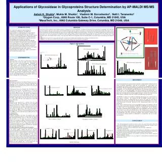
Cathode - Al. Light Emitting layer. Substrate - Glass. Fig. 3 OLED Structure. Anode - ITO. Investigation of Porphyrins in a PFO Host for Organic Light Emitting Devices Brian Tuffy* and Werner J. Blau

E N D
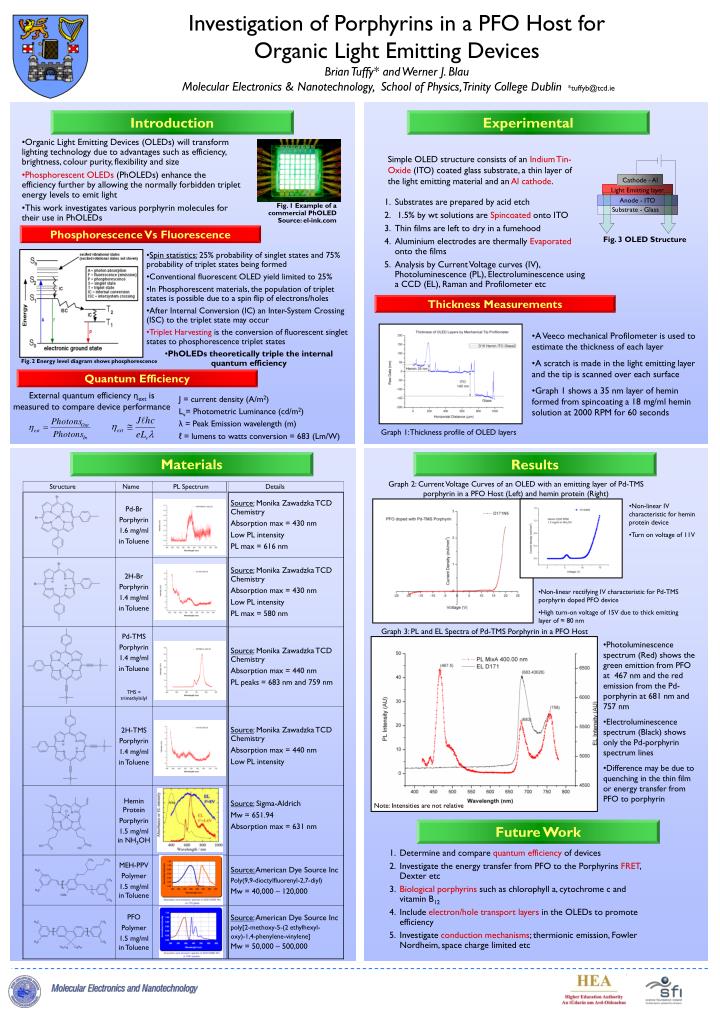
Cathode - Al Light Emitting layer Substrate - Glass Fig. 3 OLED Structure Anode - ITO Investigation of Porphyrins in a PFO Host for Organic Light Emitting Devices Brian Tuffy* and Werner J. Blau Molecular Electronics & Nanotechnology, School of Physics, Trinity College Dublin*tuffyb@tcd.ie Introduction Experimental • Organic Light Emitting Devices (OLEDs) will transform lighting technology due to advantages such as efficiency, brightness, colour purity, flexibility and size • Phosphorescent OLEDs (PhOLEDs) enhance the efficiency further by allowing the normally forbidden triplet energy levels to emit light • This work investigates various porphyrin molecules for their use in PhOLEDs Simple OLED structure consists of an Indium Tin-Oxide (ITO) coated glass substrate, a thin layer of the light emitting material and an Al cathode. • Substrates are prepared by acid etch • 1.5% by wt solutions are Spincoated onto ITO • Thin films are left to dry in a fumehood • Aluminium electrodes are thermally Evaporated onto the films • Analysis by Current Voltage curves (IV), Photoluminescence (PL), Electroluminescence using a CCD (EL), Raman and Profilometer etc Fig. 1 Example of a commercial PhOLED Source: el-ink.com Phosphorescence Vs Fluorescence • Spin statistics: 25% probability of singlet states and 75% probability of triplet states being formed • Conventional fluorescent OLED yield limited to 25% • In Phosphorescent materials, the population of triplet states is possible due to a spin flip of electrons/holes • After Internal Conversion (IC) an Inter-System Crossing (ISC) to the triplet state may occur • Triplet Harvesting is the conversion of fluorescent singlet states to phosphorescence triplet states • PhOLEDs theoretically triple the internal quantum efficiency Thickness Measurements • A Veeco mechanical Profilometer is used to estimate the thickness of each layer • A scratch is made in the light emitting layer and the tip is scanned over each surface • Graph 1 shows a 35 nm layer of hemin formed from spincoating a 18 mg/ml hemin solution at 2000 RPM for 60 seconds Fig. 2 Energy level diagram shows phosphorescence Quantum Efficiency External quantum efficiency ηextis measured to compare device performance J = current density (A/m2) Lv= Photometric Luminance (cd/m2) λ = Peak Emission wavelength (m) ℓ = lumens to watts conversion = 683 (Lm/W) Graph 1: Thickness profile of OLED layers Materials Results Graph 2: Current Voltage Curves of an OLED with an emitting layer of Pd-TMS porphyrin in a PFO Host (Left) and hemin protein (Right) Structure Name PL Spectrum Details • Non-linear IV characteristic for hemin protein device • Turn on voltage of 11V • Non-linear rectifying IV characteristic for Pd-TMS porphyrin doped PFO device • High turn-on voltage of 15V due to thick emitting layer of ≈ 80 nm Graph 3: PL and EL Spectra of Pd-TMS Porphyrin in a PFO Host • Photoluminescence spectrum (Red) shows the green emittion from PFO at 467 nm and the red emission from the Pd-porphyrin at 681 nm and 757 nm • Electroluminescence spectrum (Black) shows only the Pd-porphyrin spectrum lines • Difference may be due to quenching in the thin film or energy transfer from PFO to porphyrin Note: Intensities are not relative Future Work • Determine and compare quantum efficiency of devices • Investigate the energy transfer from PFO to the Porphyrins FRET, Dexter etc • Biological porphyrins such as chlorophyll a, cytochrome c and vitamin B12 • Include electron/hole transport layers in the OLEDs to promote efficiency • Investigate conduction mechanisms; thermionic emission, Fowler Nordheim, space charge limited etc