Download
1 / 20
210 likes | 305 Views
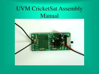
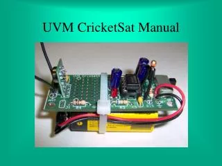
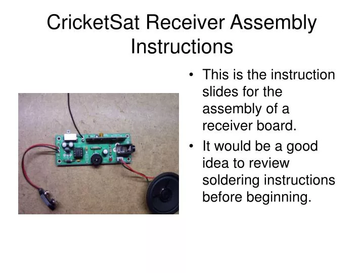
CricketSat Receiver Assembly Instructions. This is the instruction slides for the assembly of a receiver board. It would be a good idea to review soldering instructions before beginning. Receiver Parts List. R2, 680 Ohm (blue, gray, brown, gold) R3, 180K Ohm (brown, gray, yellow, gold)

E N D
CricketSat Receiver Assembly Instructions • This is the instruction slides for the assembly of a receiver board. • It would be a good idea to review soldering instructions before beginning.
Receiver Parts List • R2, 680 Ohm (blue, gray, brown, gold) • R3, 180K Ohm (brown, gray, yellow, gold) • R5, 10 Ohm (brown, black, black, gold) Optional • D1 Diode • C3, C4, and C5 capacitors, all three are 0.1 micro Farad • Switch • 8 pin Dip Socket • Red LED • C1, C2, and C6, capacitors, are all 47 micro Farad • 5 volt Regulator • 2-pin Speaker Pins • RF Receiver Module • 9 volt Battery Clip Wire • 6.25 inch Antenna Wire (1) • Audio Jack • Volume Control • LM386 Audio Amplifier Chip • Speaker • Receiver PC Board
Step 1 of 16 • Install resistors R2, R3, & R5. Solder and clip leads. R5 is optional. • Resistors are not polarized so orientation is not important. • R2, 680 Ohm (blue, gray, brown, gold) • R3, 180k Ohm (brown, gray, yellow, gold) • R5, 10 Ohm (brown, black, black, gold)
Step 2 of 16 • Install capacitors C3, C4, & C5. Solder and clip leads. • These capacitors are not polarized so orientation is not important. • All are 0.1 micro Farad capacitors (104 marking).
Step 3 of 16 • Install volume control R4. • Use masking tape if needed to hold in place for soldering. • Do not clip leads.
Step 4 of 16 • Insert diode D1. • Diode is polarized. Install with white band oriented as shown. • Look at the PC board to see the direction of the white band. • Solder and clip leads.
Step 5 of 16 • Install switch. • Use masking tape if needed to hold in place for soldering. • Solder all eight leads. • Do not clip leads.
Notch Step 6 of 16 • Install 8 pin DIP socket for U3. • Insert all pins of the socket, notch is pointing up. • Make sure all pins go through the board before soldering all pins. • Socket will snap in to place. • Do not clip wires.
Step 7 of 16 • Install red LED in D2. • The LED is polarized, the long lead wire is positive. Look at the PC board for correct alignment. • Insert flush to board. • Solder and clip leads.
White band Step 8 of 16 • Install capacitors C1, C2, & C6. • The capacitors are polarized. The side with the white band is negative. The positive lead is longer. Look at the board for +/- signs. • Solder and clip leads. • All of these capacitors are all 47 micro Farad.
Step 9 0f 16 • Install the 5 volt regulator in U1. • The regulator is polarized and should be installed with the flat side facing away from the switch. • Do not push flat to the board, allow the regulator to stand up on the board. • Solder and clip leads.
Step 10 of 16 • Install 2 pin speaker jack in J2. • Insert with longer leads on top of the PC board and solder shorter leads on bottom of board. • Do not clip any of these leads.
Step 11 of 16 • Install audio jack J1. • Use masking tape to hold in place while soldering if needed. • Solder the three leads. Holes are oversized and can be partially filled with solder to hold in place. • Pins may be clipped.
Next Step Special Note • The next component to install is the radio receiver module. Care should be taken to orient this component correctly. • You will have one of two different radio receiver modules, one without the silver “can” and one with. • Both components operate exactly the same, they just look different. No Silver can Silver can
Step 12 of 16 • Install receiver module U2 into circuit board. • Orient as shown with the module components facing outward on board. The silver “can” on some components should face inward. • Solder and clip all eight leads.
Step 13 of 16 • Push 2” of battery clip wires down through the inner strain relief holes. • The red lead goes through the hole near the B+ hole and the black lead goes through the inner hole near the B- hole. • Push the bare ends of the wires back up and through the B+ & B- holes. • Leave small loops and solder the bare ends on top of the PC board. • Pull the wires tight to remove the loops.
Step 14 of 16 • Insert bare end of the antenna wire into smaller hole from under side. • Solder on top of the PC board and clip lead. • Push free end of the wire up through inner hole and pull tight. • Orient antenna wire to be vertical.
Notch Step 15 of 16 • Install Integrated Chip U3 into the socket. • The chip pins may be flared out & may need to be bent slightly inward. • Make sure the chip notch is facing upward to match the socket notch. • Press firmly in place. • No soldering, no clipping.
Step 16 of 16 • Attach the speaker to J2. • Orientation of speaker wires is not important. • Align the holes in the white connector to pins on the circuit board. • Press firmly into place.
Testing • Slide the power switch to off. • Attach a 9 volt battery. • Slide power to on. • LED will blink when a signal is received. • With a transmitter turned on sending a signal, you should hear a faint tone once every 20 – 30 secs.