Download
1 / 18
180 likes | 301 Views
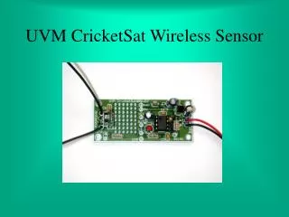
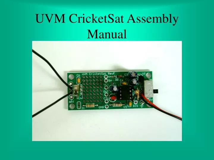
UVM CricketSat Assembly Manual. Make a hard copy print out of the following page It will help you identify the proper components Place the components on top of the matching picture on the sheet Generally, the lowest profile components are added to the board first

E N D
Make a hard copy print out of the following page It will help you identify the proper components Place the components on top of the matching picture on the sheet Generally, the lowest profile components are added to the board first Many components need to be properly orientated Pay close attention to instructions concerning the proper placement of those components Use safety glasses while assembling the CricketSat. Hot solder and flying leads can injure your eyes. Getting Started
R4: 100 Ohm C1 C2 C3 C4 C5 C6 Negative White Band Brown-Black-Brown-Gold R2: 3300 Ohm 0.1 micro-Farad Capacitors Orange-Orange-Red-Gold Black Band D2 - Diode + - + - + - - + R3: 680 Ohm Longer Lead Notch 47 micro-Farad Electrolytic Capacitors Dimple Blue-Gray-Brown-Gold Pin 1 1234 8765 D1 U3: RF Transmitter DIP Socket U1: 555 Timer IC R1 U2 SW1 Flat Side Up Longer Lead Pins: 1 2 3 Pins: 1 2 3 4 - 10K Ohm Thermistor + On/Off Switch 5-Volt Regulator Light Emitting Diode (LED) B1: 9-Volt Battery - Printed Circuit Board (PCB) + Red Lead is Positive Battery Snap Connector Antenna Wires - +
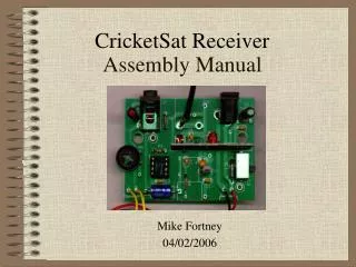
Printed Circuit Board • Metal layers - conductors • Front and back sides • Epoxy board - insulator • Traces provide the wiring • Via holes - connect the front and back metal layers • Front side of board • Components on this side • White silkscreen layer • Component outlines • Reference designators • Green solder mask layer • Insulates exposed metal • Back side of board • Solder on this side
Assembly Techniques 45 degree angle is best • Inserting Devices • Bend leads if necessary to ease insertion into board • While pressing component to board, bend leads at an angle • This will hold components in place while soldering • Just 4 or 5 components at a time Bend lead close to board • Soldering • Use enough heat • A shiny Hershey’s Kiss shape • Snipping leads • Flying leads may damage eyes! • Hold lead while cutting or point downward Snip just above solder joint
Resistors and Diode First D2 - Orange Diode (Black Band to the Left) R4 - 100 Ohms R3 - 680 Ohms R2 - 3300 Ohms Clip leads after this step...
Small Capacitors and Battery Clip Route wire down through these center holes Solder wire to these outer holes Top View • Install Battery Clip • Feed 2 inches of wire down through strain relief holes, from top side of board • Push bare wire ends completelyup through solder pad holes from bottom side of board • Pull excess wire tight. Should look like this… • Solder connection on top side of the board • Trim excess wire on top of board Red + Black - Bottom View Install Capacitors C4, C5, C6 0.1 uF Clip leads... No Bare Wire Allowed
DIP Socket • Align socket with white outline provided on board • Place the notch up, towards C4 • On/Off Switch outline for next step... • Use the vise alligator clip to hold the socket in place or press flat against table surface while soldering • Make sure that socket is flat to the circuit board and that all the pins emerge from the backside of the board before soldering in place
On/Off Switch Solder all eight pins of the switch • Use the vise alligator clip to hold the switch in place or press flat against table surface while soldering • Make sure that switch is flat to the circuit board and that all the pins emerge from the backside of the board before soldering in place
Installing the Taller Parts U2 - Voltage Regulator Push only half-way into board • Install these Parts... • C1, C2, C3 -Polarized • White band (-) to outside of board • U2 - Orientation • Flat side left, towards C3 • Push only half-way into board • D1 LED -Polarized • Longer lead (+), next to socket Make sure capacitors are mounted close to board surface to minimize movement Clip leads...
Install the Antenna Wires • There are four antenna holes • Wires are soldered to the outer two holes, and pass through the outer two • Strip ½” of insulation from end of wires • Insert a bare wire end from the bottom side of the board through one of the two outer white-circled antenna holes • Rest it on a table surface as shown left • The weight of the board should insure that all of the bare wire extends through the top of the board • In this position, solder the connection on the top of the board as shown • Repeat for the other wire • Feed the free ends of the wires through the inner strain relief holes from the bottom side of the board • Pull tight and snip excess bare wire on top of board Top View No bare wires through the strain relief holes Bottom View
Transmitter and Timer IC Transmitter Module • Install the transmitter as shown to the left • Metal can faces towards antenna • Make sure the module is soldered close to the board to minimize movement Clip your leads... 555 Timer IC • Locate Pin 1 on the IC, marked with a “dot” • This end of the IC goes next to C4 • Straighten pins if necessary and press into socket • If pins bend while inserting into socket, remove IC and straighten pins.
Finally, the Thermistor • Stands up above other circuits • Use the black plastic insulation that you stripped from your antenna wires in an earlier step • Slide insulation up to the body of the thermistor in order to insulate the leads • Insulation prevents “short circuits” to other exposed metal leads Solder at location R1 on the circuit board
Short Circuit Test • We want to make sure that there are no short circuits on the board • Performed before connecting the battery for the first time • Set the meter to the OHMS setting • Touch the meter leads to the battery connector as shown • Meter should indicate an open circuit • Reverse the test leads and measure again • Should be an open circuit reading again
Live Test • Connect the 9-Volt battery • Observe the LED, it should be flashing around 1-2 Hertz (times per second) • RF Test: Use a UHF radio receiver tuned near 434 MHz to hear pulses • Optional: Measure the voltage on the V+ and 5V test points Congratulations on your successful assembly!
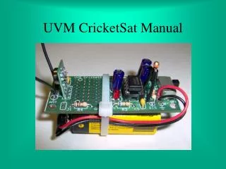
Primary Features Prototype Development Area 555 Timer IC 5-Volt Regulator IC Timing Capacitor On/Off Switch Dipole Antenna 9-Volt Battery Leads Thermistor Test Points RF Transmitter Module Timing Resistor Flashing LED
Secondary Features Noise Decoupling Capacitor Protection Diode (Reverse Battery Connection) Noise Decoupling Capacitors Current Limiting Resistor (LED) Noise Decoupling Capacitor Output Jack Series Isolation Resistor