Download
1 / 27
320 likes | 872 Views
Instructions and Instruction Sequencing. Tasks carried out by the computer a sequence of small steps The computer has instructions that perform four types of operations:. Data transfer between memory and processor registers Arithmetic and logic operations on data

E N D
Instructions and Instruction Sequencing Tasks carried out by the computer a sequence of small steps The computer has instructions that perform four types of operations: • Data transfer between memory and processor registers • Arithmetic and logic operations on data • Program sequencing and control • I/O transfers Fall 2009
Register Transfer Notation Names for addresses of memory locations • LOC, PLACE, A, VAR2, etc. Names for processor registers • R0, R5, R10, etc.. Names for I/O registers • DATAIN, OUTSTATUS, etc The contents of a location are denoted by placing brackets around the name of the location Contents of registers R1 and R2 are added and the sum is placed in register R3 Contents of memory location LOC are transferred to processor register R1 Fall 2009
RTN This notation is known as Register Transfer Notation (RTN) right-hand side denotes a VALUE and the left-hand side denotes a LOCATION Fall 2009
Assembly Language Notation Use a different notation for machine instructions and programs – we use Assembly Language The contents of a location LOC is moved to processor register R1 The contents of LOC is unchanged – the contents of R1 are overwritten Contents of registers R1 and R2 are added and the sum is placed in register R3 Fall 2009
Basic Instruction Types In a high-level language, add A and B and assign to C To carry out this instruction • Contents of memory locations A and B are fetched • And transferred to the processor • Sum is computed by the ALU • Result stored back to memory in location C • During compilation, • A, B and C are assigned memory locations • The names (A,B and C) refer to the memory locations • The contents of the memory locations are the values of A, B and C To carry out this, this must occur Fall 2009
Basic Instruction Types Given an instruction such as To treat this as a SINGLE instruction - A and B, the source operands, and C, the destination operand, would all have memory locations Therefore, the ENCODED form of this single instruction must contain addresses for A,B and C, and also contain the “code” for Add – this could be TOO large to fit to fit into a typical 32-bit word – processor word Therefore, we could try using a sequence of simpler instructions to perform the same task (and therefore, the processor word would require less space for 2 addresses and the code for Add or Move) Add A to B and store result in B Copy B’s content to C location – leaving B content unchanged Add A to C and store result in C Fall 2009
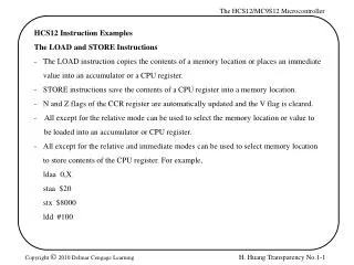
Basic Instruction Types The 2-address instruction could also NOT fit into one word Therefore, we could try using a sequence of even simpler instructions to perform the same task - SINGLE ADDRESS type instructions - (and therefore, the processor word would require less space for 1 address and the code for Add, Load and Store) Copies the contents of memory location A into the accumulator – single address instructions a processor register called the accumulator Add the content of memory location B to the contents of the accumulator register Copies content of the accumulator to memory location C NOTE1: for LOAD – the accumulator is the destination location NOTE2: for STORE – the accumulator is the source location Fall 2009
ACC Register • The accumulator is considered a general purpose register – most computers have 8 to 32 – so a small number of bits are needed in the instruction specify the which register • Instead of above, a more general way the instructions would appear with variable registers: Fall 2009
Basic Instruction Types When computer uses multiple general purpose registers, many instructions involve operands in REGISTERS versus REGISTERS and MEMORY or These instructions can usually fit into one word because register names are being used in the instruction – thus requiring less space Note, is the same as Register to memory Note, is the same as memory to register Fall 2009
Basic Instruction Types Therefore in using MOVE versus LOAD or STORE, the instructions for C= A + B would be: Faster than If only one operand was allowed and could use memory and registers If only one operand was allowed and only using registers Fall 2009
Pushdown Stack For the 3-address, 2-address and 1-address instructions, the memory locations of the operands are explicitly defined. There are instructions that use memory locations for operands that are implicitly defined – zero-address instructions – operands are stored in pushdown stacks. Fall 2009
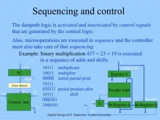
Instruction Straight-line Sequencing Given one operand per instruction, a number of processor registers, a word length of 32 bits, byte addressable memory, the following example shows how a 3-instruction program could look like in memory. Each instruction uses 4-bytes • The Program Counter (PC) contains the address of the next instruction – initially, the 1st instruction • Control unit circuits use the PC’s info to fetch and execute the instructions – one at a time • Executing the instruction is in 2 phases: • 1. instruction is fetched from memory location – instruction is then placed in instruction register (IR) – called instruction fetch phase • 2. instruction in the IR is examined to determine which operation – then the processor performs the operation – called instruction execute phase • The PC incremented to point to the next instruction Fall 2009
Branching Consider the task of adding a list of n numbers. Separate “Add” instructions are used to add NUM1, NUM2, …. NUMn to the contents of register R0, then the contents of R0 is stored to memory location SUM Fall 2009
Straightline Sum Fall 2009
Looping • Use a single “Add” instruction in a program loop – starts at location LOOP and ends at Branch on GT 0 • Initially the contents of N (# of entries) is loaded in register R1 – R1 is used as the counter • If branch is greater than 0, control jumps to LOOP – if branch is not greater than 0, PC is incremented in its normal way Fall 2009
Implementing a Loop Fall 2009
Condition Codes The way the processor keeps track of information for the conditional branches is via the condition code flags These flag bits reside in a register called the condition code register or status register. Some common flags are: Fall 2009
Memory Addressesing (1) During each loop iteration, a value at a different location address is added (2) Therefore the address is changing during each iteration to point at the new value (3) In this case, the address needs to be incremented by 4 during each iteration to point at the new value (4) Therefore the address can be placed in a register – by doing so, the address can be incremented by 4 during each iteration The ability to have flexibility in specifying the address of an operand is called Addressing Modes Fall 2009
Addressing Modes • High level programs use constants, local and global variables, pointers and arrays • When translating the high-level program into assembly language, the compiler must be able to implement the various constructs (ie. arrays, etc) • Therefore, the instruction set must have the ability to specify the location of the operand in different ways – called Addressing Modes Fall 2009
Addressing Modes – Variables and Constants • Regarding Variables • Register Mode – operand resides in a processor register, and the address/name of the register is used in the instruction • Absolute Mode – operand resides in memory, and the address of the location is explicitly used in the instruction Note: Highlevel language declaration – compiler allocate memory locations for A and B example • Regarding Constants • Immediate Mode – immediate mode used for both address and data constants – operand is given explicitly in the instruction (ie. Move 200, R0 – places the value of 200 in register R0 – a common convention to denote an actual value is #200 – Move #200,R) Highlevel code produces Fall 2009
Addressing Modes – Indirection and Pointers • Regarding Indirection and Pointers • The instruction does NOT give the operand or its address explicitly • The instruction provides info from which the memory address of the operand can be determined – called the effective address • Indirect Mode – effective address of the operand is the contents of a register or memory location whose address appears in the instruction • Denote “indirection” by placing the register or memory location in parentheses For this “ADD”, processor uses the value of B which is in register R1, as the effective address of the operand – the address where the operand can be found Can also do “indirection” using a memory location The register or memory location containing the address of the operand is called a pointer Fall 2009
Addressing Modes – Indirection and Pointers Indirect addressing can be used to access successive numbers in a list This part of the code can now be R2 acts as the pointer Fall 2009
Addressing Modes – Indexing and Arrays • Regarding Indexing and Arrays • Index Mode – effective address of the operand is generated by adding a constant value to the contents of a register • A set of registers are used to implement this – called an index register • Nomenclature is where X denotes the constant value and Ri is the register name • The contents of the index register is not changed when generating the effective address Fall 2009
Addressing Modes – Indexing and Arrays One approach to index mode Index register, R1, contains the address of the memory location, and the value X (20 in this case) defines an offset from the address to the location where the operand is found Another approach to index mode The constant X (20 in this case) corresponds to a memory address and the contents of the Index Register define the offset to the operand In both cases – the effective address is the sum of two values – one given explicitly in the instruction and the other stored in a register Fall 2009
Addressing Modes - Other • Auto-increment Mode – effective address of the operand is the content of a register specified in the instruction – after accessing the operand, the contents of this register is automatically incremented to point to the next item in the list • Auto-decrement Mode –the contents of a register specified in the instruction are first automatically decremented and are then used as the effective address of the operand Fall 2009