Download
1 / 20
281 likes | 492 Views
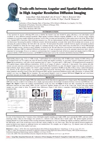
Imaging with High Spatial and Temporal Resolution Microchannel Plate Detectors Oswald, H.W. Siegmund (1), John, V. Vallerga, (1), Anton. S. Tremsin (1), Jason McPhate (1), Adrian Martin (2), Bruce Feller (3), Muhammad Arif (4), Daniel Hussey (4), David Jacobson (4).

E N D
Imaging with High Spatial and Temporal Resolution Microchannel Plate Detectors Oswald, H.W. Siegmund (1), John, V. Vallerga, (1), Anton. S. Tremsin (1), Jason McPhate (1), Adrian Martin (2), Bruce Feller (3), Muhammad Arif (4), Daniel Hussey (4), David Jacobson (4). Space Sciences Laboratory, University of California, Berkeley, CA, 94720 (1), Sensor Sciences LLC, 3333 Vincent Road, Suite 103, Pleasant Hill, CA 94523 (1), Nova Scientific Inc. 10 Picker Road, Sturbridge, MA 01566 (2), NIST, Ionizing Radiation Division, 100 Bureau Dr. Gaithersburg, MD 20899 (3) O. Siegmund, WCNR-8
MCP Detector Anodes Event based (e.g.delayline, cross-strip) X,Y,T of each event Timing to ~100 ps High spatial resolution (MCP pore) Coincidence/Anti-coincidence tools Flux up to ~ MHz Integrating (Intensifier-CCD, Medipix) Histogram X,Y T from frame readout High flux capability (GHz) O. Siegmund, WCNR-8
Microchannel Plate Detectors The general scheme is photon conversion (photocathode) or direct detection (ions/e-), 1, 2 or 3 MCPs to provide gain, and then some type of readout. For Neutron detection and imaging we have used and open face detector with MCP triple stacks and an event counting/imaging cross delay line anode Window/cathode MCPs Anode 25mm cross delay line anode detector showing anode (left), and neutron sensitive MCPs (right) O. Siegmund, WCNR-8
Detection of Neutrons in MCPs Absorption of Neutron Secondary(s) reaching surface Emission of photoelectron Electron gain above electronic threshold B14 MCP types use Gadolinium n + 157Gd 158Gd + γ's + X-rays + e- (29 keV - 182 keV, ~75%) σ = 70,000 b at 1 Å n + 155Gd 156Gd + γ's + X-rays + e- (39 keV - 199 keV; ~75%) σ = 17,000 b at 1 Å HB4 MCP types use Boron n + 10B 7Li (1.0 MeV) + 4He (1.8 MeV) 7% n + 10B 7Li (0.83 MeV) + 4He (1.47 MeV)+ γ (0.48 MeV) 93% σ = 2100 b at 1 Å O. Siegmund, WCNR-8
Cross Delay Line MCP Detectors Typical characteristics Sealed tube or open face. MCPs, gain ~107 Photon, ion, electron, neutron sensing, size formats to 100mm, Resolution ~20µm Event rates to >1 MHz, (kHz/pixel rates) Timing <100ps (~20ps limit) Charge cloud Cross delay line anode is a multi-layer crossed conductor layout. Period is ~0.5mm on ceramic. MCP charge divides between upper and lower charge collectors, Event centroids are linearly proportional to signal arrival time difference at ends of delay lines. Fast event propagation (50 ns). Compact and robust (900°C). O. Siegmund, WCNR-8
Cross Delay Line Electronic Readout System The cross delay line electronics consists of fast amplifiers for the four anode signals followed by constant fraction discriminators and time to digital converters to provide X, Y event positions. Single event time stamping to 25ns, and to 20ps when using a second TDC unit. TDC unit 13 bit X,Y 15ps FWHM 32 bit T, 25ns LSB 0.4µs deadtime (1 MHz @ 30%) O. Siegmund, WCNR-8
Gain and Background for B14 MCPs • UV interacts at the top of the MCP stack, producing photoelectrons thatinitiate full gain electron avalanche multiplication with tight PHDs. Gain and PHD behavior is similar to normal glass MCPs. • Background event rate is very low < 0.04 events cm-2 sec-1 since there are no radioactive materials in the glass. B14 MCP stack of 3 plates, 1000 sec integration, one “warm” spot. B14 MCP stack of 3 plates O. Siegmund, WCNR-8
Amplitude Distributions for Radiation • UV interacts at the top of the MCP stack, producing photoelectrons thatinitiate full gain electron avalanche multiplication with tight PHDs • Gamma events (60Co, 137Cs) interact throughout the MCP stack causing a wide range (exponential) of gain values for events HB4 MCP + 2 glass MCPs HB4 MCP + 2 glass MCPs at MNRC O. Siegmund, WCNR-8
MCP - Cross Delay Line Imaging B14 MCP Z stack and 32mm XDL anode measurements of spatial resolution indicate ~23 µm FWHM for ~107 gain. B14 MCP Z stack and 32mm XDL anode. Deep (108 count) image section accumulation, shows few defects and little fixed pattern noise Air force test pattern image B14 MCP stack UV image shows MCPedge pattern. O. Siegmund, WCNR-8
NIST NCNR BT6 Beam Line Tests Image of Cd test target with Neutrons (>4.8 x 106 cm-2 s-1, 1.6Å) at NIST using XDL detector with neutron sensitive MCPs, <25µm rms resolution. Image using Gadolinium MCPs Image using Boron MCPs Mask: 1mm thick Cd 6.5mm star pattern, 165µm wide bars PHDs for through, and under mask,gammas dominate at high amplitudes PHDs for through, and under mask. Neutron (alpha) events give high amplitudes. O. Siegmund, WCNR-8
NG6-M Beam Line Boron MCPs Image of Cd test target with Neutrons (~105 cm-2 s-1, 5Å) at NIST using XDL detector with neutron sensitive Boron MCPs, 17µm rms resolution. PHDs for through, and under mask.Neutron (alpha) events give high amplitudes. Gamma flux is much lower at NG6 so that neutron detections dominate the distribution. Image using Boron MCPs Image slice across one arm of the star pattern. Contrast is poor if all events, or only high amplitude events are used. Using only the low amplitude peak events gives a high contrast (30:1) image at the expense of some efficiency. O. Siegmund, WCNR-8
BT6 Beam Line Tests - Spatial Resolution Spatial resolution was estimated from histogram fits to the star pattern arms. Best case values were about 21 & 23µm RMS for the B14 stack and for the HB4 stack. 21µm • B14 MCP stack 23µm • HB4 MCP stack O. Siegmund, WCNR-8
NG6-M Beam Line Tests - Spatial Resolution Lower gamma flux at the NG6-M beam and better beam collimation and lower energy gives better contrast than the BT6 beam Cd mask image for HB4 (Boron) MCP Cross delay line detector Histogram of horizontal bar gives ~17µm RMS resolution O. Siegmund, WCNR-8
NG6-M Beam Line Tests - Water imaging No water in sample A phantom object with water flow was imaged to assess the fidelity of the detector 3.2mm Water added Water at higher pressure O. Siegmund, WCNR-8
Neutron Detection Efficiency BT6, 4.8 x 106 cm-2 s-1, 1.6Å, -HB4 efficiency 21% -B14 efficiency 18% The efficiencies are lower than can be achieved given the interaction cross sections. The MCP configuration can be improved in the future to enhance the practical efficiency. O. Siegmund, WCNR-8
Cross strip readout detectors 32mm x 32mm XS anode, 0.5mm period Cross strip is a multi-layer cross finger layout. Fingers have ~0.5mm period on ceramic. Charge spread over 3-5 strips per axis, Event position is derived from charge centroid. Anodes up to 45 x 45mm have been made. Signals brought to backside by hermetic vias Compact and robust (700°C). Can encode multiple simultaneous events. Fast event propagation (few ns). Intrinsic speed supports >10 MHz rates Low gain, 1/100 of delay line Very high resolution, <5µm O. Siegmund, WCNR-8
NG6-M Beam Line B14 MCPs in XS Detector • Spatial resolution is improved to ~15.5µm RMS for the neutron flux image with intrinsic resolution of <10µm. Spatial resolution is dominated by the Cd mask alignment and neutron beam depth interaction in the MCP converter. O. Siegmund, WCNR-8
Neutron MCPs with Medipix Readout Medipix/MCP hybrid originally developed for noiseless, fast readout optical detector for adaptive optics Medipix readout allows high flux and frame rate Open face “demountable” detector MCPs removed showing Medipix O. Siegmund, WCNR-8
Cd mask images in thermal neutron beam 630 m slots and bars in Cd mask imaged at MNRC Low event threshold High event threshold O. Siegmund, WCNR-8
Summary 10B and Gd doped MCPs are a new tool for imaging neutrons with high resolution and efficiency Imaging MCP detector technology allows flexible and sophisticated techniques to match the sensor to the application Optimization of the MCP physical parameters to improve sensitivity are continuing, but existing plates are already quite good and available O. Siegmund, WCNR-8