Download
1 / 27
270 likes | 356 Views
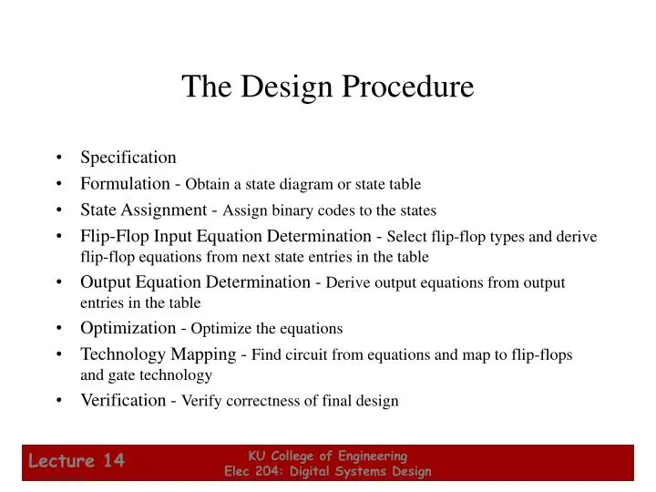
The Design Procedure. Specification Formulation - Obtain a state diagram or state table State Assignment - Assign binary codes to the states Flip-Flop Input Equation Determination - Select flip-flop types and derive flip-flop equations from next state entries in the table

E N D
The Design Procedure • Specification • Formulation - Obtain a state diagram or state table • State Assignment - Assign binary codes to the states • Flip-Flop Input Equation Determination - Select flip-flop types and derive flip-flop equations from next state entries in the table • Output Equation Determination - Derive output equations from output entries in the table • Optimization - Optimize the equations • Technology Mapping - Find circuit from equations and map to flip-flops and gate technology • Verification - Verify correctness of final design KU College of Engineering Elec 204: Digital Systems Design
Formulation: Finding a State Diagram • A state is an abstraction of the history of the past applied inputs to the circuit (including power-up reset or system reset). • The interpretation of “past inputs” is tied to the synchronous operation of the circuit. E. g., an input value (other than an asynchronous reset) is measured only during the setup-hold time interval for an edge-triggered flip-flop. • Examples: • State A represents the fact that a 1 input has occurred among the past inputs. • State B represents the fact that a 0 followed by a 1 have occurred as the most recent past two inputs. KU College of Engineering Elec 204: Digital Systems Design
Formulation: Finding a State Diagram • In specifying a circuit, we use states to remember meaningful properties of past input sequences that are essential to predicting future output values. • A sequence recognizer is a sequential circuit that produces a distinct output value whenever a prescribed pattern of input symbols occur in sequence, i.e, recognizes an input sequence occurence. • We will develop a procedure specific to sequence recognizers to convert a problem statement into a state diagram. • Next, the state diagram, will be converted to a state table from which the circuit will be designed. KU College of Engineering Elec 204: Digital Systems Design
Sequence Recognizer Procedure • To develop a sequence recognizer state diagram: • Begin in an initial state in which NONE of the initial portion of the sequence has occurred (typically “reset” state). • Add a state that recognizes that the first symbol has occurred. • Add states that recognize each successive symbol occurring. • The final state represents the input sequence (possibly less the final input value) occurence. • Add state transition arcs which specify what happens when a symbol not in the proper sequence has occurred. • Add other arcs on non-sequence inputs which transition to states that represent the input subsequence that has occurred. • The last step is required because the circuit must recognize the input sequence regardless of where it occurswithin the overall sequence applied since “reset.”. KU College of Engineering Elec 204: Digital Systems Design
State Assignment • Each of the m states must be assigned a unique code • Minimum number of bits required is n such thatn ≥ log2mwhere x is the smallest integer ≥ x • There are useful state assignments that use more than the minimum number of bits • There are 2n - m unused states KU College of Engineering Elec 204: Digital Systems Design
Sequence Recognizer Example • Example: Recognize the sequence 1101 • Note that the sequence 1111101 contains 1101 and "11" is a proper sub-sequence of the sequence. • Thus, the sequential machine must remember that the first two one's have occurred as it receives another symbol. • Also, the sequence 1101101 contains 1101 as both an initial subsequence and a final subsequence with some overlap, i. e., 1101101 or 1101101. • And, the 1 in the middle, 1101101, is common in both subsequences. • The sequence 1101 must be recognized each time it occurs in the input sequence. KU College of Engineering Elec 204: Digital Systems Design
1/0 A B Example: Recognize 1101 • Define states for the sequence to be recognized: • assuming it starts with first symbol, • continues through each symbol in the sequence to be recognized, and • uses output 1 to mean the full sequence has occurred, • with output 0 otherwise. • Starting in the initial state (Arbitrarily named "A"): • Add a state that recognizes the first "1." • State "A" is the initial state, and state "B" is the state which represents the fact that the "first" one in the input subsequence has occurred. The output symbol "0" means that the full recognized sequence has not yet occurred. KU College of Engineering Elec 204: Digital Systems Design
1/0 1/0 A B C 1/1 1/0 0/0 1/0 D A B C Example: Recognize 1101 (continued) • After one more 1, we have: • C is the state obtained when the input sequence has two "1"s. • Finally, after 110 and a 1, we have: • Transition arcs are used to denote the output function (Mealy Model) • Output1on the arc from D means the sequence has been recognized • To what state should the arc from state Dgo? Remember: 1101101 ? • Note that D is the last state but the output 1 occurs for the input applied in D. This is the case when a Mealy model is assumed. KU College of Engineering Elec 204: Digital Systems Design
1/1 1/0 0/0 1/0 A B C D 1/0 0/0 1/0 A B C D 1/1 Example: Recognize 1101 (continued) • Clearly the final 1 in the recognized sequence 1101 is a sub-sequence of 1101. It follows a 0 which is not a sub-sequence of 1101. Thus it should represent the same state reached from the initial state after a first 1 is observed. We obtain: KU College of Engineering Elec 204: Digital Systems Design
1/0 0/0 1/0 A B C D 1/1 Example: Recognize 1101 (continued) • The state have the following abstract meanings: • A: No proper sub-sequence of the sequence has occurred. • B: The sub-sequence 1 has occurred. • C: The sub-sequence 11 has occurred. • D: The sub-sequence 110 has occurred. • The 1/1 on the arc from D to B means that the last 1 has occurred and thus, the sequence is recognized. KU College of Engineering Elec 204: Digital Systems Design
Example: Recognize 1101 (continued) • The other arcs are added to each state for inputs not yet listed. Which arcs are missing? • Answer: "0" arc from A "0" arc from B "1" arc from C "0" arc from D. 1/0 0/0 1/0 A B C D 1/1 KU College of Engineering Elec 204: Digital Systems Design
0/0 1/0 1/0 0/0 1/0 A B D 0/0 1/1 0/0 Example: Recognize 1101 (continued) • State transition arcs must represent the fact that an input subsequence has occurred. Thus we get: • Note that the 1 arc from state C to state C implies that State C means two or more 1's have occurred. C KU College of Engineering Elec 204: Digital Systems Design
0/0 0/0 1/0 1/0 0/0 1/0 1/0 A B C D 0/0 1/1 0/0 Present Next State Output State x=0 x=1 x=0 x=1 0 0 A B A B C D Formulation: Find State Table • From the State Diagram, we can fill in the State Table. • There are 4 states, one input, and one output. We will choose the form with four rows, one for each current state. • From State A, the 0 and1 input transitions have been filled in along with the outputs. KU College of Engineering Elec 204: Digital Systems Design
0/0 1/0 1/0 0/0 1/0 A B C D 0/0 1/1 0/0 Formulation: Find State Table • From the state diagram, we complete the state table. • What would the state diagram and state table look like for the Moore model? Present Next State Output State x=0 x=1 x=0 x=1 A A B 0 0 B A C 0 0 C D C 0 0 D A B 0 1 KU College of Engineering Elec 204: Digital Systems Design
Example: Moore Model for Sequence 1101 • For the Moore Model, outputs are associated with states. • We need to add a state "E" with output value 1 for the final 1 in the recognized input sequence. • This new state E, though similar to B, would generate an output of 1 and thus be different from B. • The Moore model for a sequence recognizer usually has more states than the Mealy model. KU College of Engineering Elec 204: Digital Systems Design
0 1 0 1 1 A/0 B/0 C/0 D/0 0 1 1 0 E/1 0 Example: Moore Model (continued) • We mark outputs on states for Moore model • Arcs now show only state transitions • Add a new state E to produce the output 1 • Note that the new state, E produces the same behavior in the future as state B. But it gives a different output at the present time. Thus these states do represent a different abstraction of the input history. KU College of Engineering Elec 204: Digital Systems Design
0 1 0 1 1 A/0 B/0 C/0 D/0 0 1 1 0 E/1 0 Present Next State Output State x=0 x=1 y A A B 0 B A C 0 C D C 0 D A E 0 E A C 1 Example: Moore Model (continued) • The state table is shown below • Memory requires more states in the Moore model: “Moore is More.” KU College of Engineering Elec 204: Digital Systems Design
Present Next State Output State x=0 x=1 x=0 x=1 A A B 0 0 B A B 0 1 State Assignment – Example 1 • How may assignments of codes with a minimum number of bits? • Two – A = 0, B = 1 or A = 1, B = 0 • Does it make a difference? • Only in variable inversion, so small, if any. KU College of Engineering Elec 204: Digital Systems Design
Present Next State Output State x=0 x=1 x=0 x=1 A A B 0 0 B A C 0 0 C D C 0 0 D A B 0 1 State Assignment – Example 2 • How may assignments of codes with a minimum number of bits? • 4 3 2 1 = 24 • Does code assignment make a difference in cost? KU College of Engineering Elec 204: Digital Systems Design
State Assignment – Example 2 (continued) • Assignment 1: A = 0 0, B = 0 1, C = 1 0, D = 1 1 • The resulting coded state table: KU College of Engineering Elec 204: Digital Systems Design
State Assignment – Example 2 (continued) • Assignment 2: A = 0 0, B = 0 1, C = 1 1, D = 1 0 • The resulting coded state table: KU College of Engineering Elec 204: Digital Systems Design
X X X 0 0 0 0 0 1 0 0 0 0 1 0 Y2 Y2 Y2 0 0 0 0 1 0 Y1 Y1 Y1 1 0 1 1 1 0 Find Flip-Flop Input and Output Equations: Example 2 - Assignment 1 • Assume D flip-flops • Interchange the bottom two rows of the state table, to obtain K-maps for D1, D2, and Z: D1 Z D2 KU College of Engineering Elec 204: Digital Systems Design
X X X 0 0 0 1 0 0 0 0 0 0 1 0 Y2 Y2 Y2 0 0 0 0 0 1 Y1 Y1 Y1 1 0 1 1 1 0 Optimization: Example 2: Assignment 1 D1 Z D2 • Performing two-level optimization: D1 = Y1Y2 + XY1Y2D2 = XY1Y2 + XY1Y2 + XY1Y2Z = XY1Y2 Gate Input Cost = 22 KU College of Engineering Elec 204: Digital Systems Design
X X X 0 0 0 0 1 0 0 0 0 0 1 1 Y2 Y2 Y2 0 0 1 0 1 1 Y1 Y1 Y1 0 0 0 1 1 0 Find Flip-Flop Input and Output Equations: Example 2 - Assignment 2 • Assume D flip-flops • Obtain K-maps for D1, D2, and Z: D1 Z D2 KU College of Engineering Elec 204: Digital Systems Design
X X X 0 0 0 1 0 0 0 0 0 1 1 0 Y2 Y2 Y2 0 0 1 1 0 1 Y1 Y1 Y1 0 0 0 0 1 1 Optimization: Example 2: Assignment 2 D1 Z D2 • Performing two-level optimization: D1 = Y1Y2 + XY2 Gate Input Cost = 9D2 = X Select this state assignment for Z = XY1Y2 completion of the design KU College of Engineering Elec 204: Digital Systems Design
Y1 D C R Z Y2 D X Clock C R Reset Map Technology • Initial Circuit: • Library: • D Flip-flopswith Reset(not inverted) • NAND gateswith up to 4inputs andinverters KU College of Engineering Elec 204: Digital Systems Design
Y1 D C R Z Y2 D X C Clock R Reset Mapped Circuit - Final Result KU College of Engineering Elec 204: Digital Systems Design