Download
1 / 45
570 likes | 991 Views
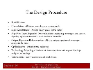
Procedure Design Considerations. BEIJING, CHINA; 30 JUN-11 JUL 2014. Learning Objectives. By the end of this presentation you should understand: Procedure design considerations including : Path Terminators Waypoint Types Factors affecting turn radius. Conceptual Design: What Next?.

E N D
Procedure Design Considerations BEIJING, CHINA; 30 JUN-11 JUL 2014
Learning Objectives • By the end of this presentation you should understand: • Procedure design considerations including: • Path Terminators • Waypoint Types • Factors affecting turn radius
Waypoints PBN Route Using Waypoints
Path Terminators Altitude A Distance C DME distance D Fix F Next leg I Manual termination M Radial termination R Terminator Path Constant DME arc A C Course to D Direct Track F Course from a fix to Holding pattern H I Initial R Constant radius T Track between V Heading to
Path Terminators • Track to Fix - TF • Direct to Fix - DF • Course to Fix - CF • Fix to Altitude - FA • Course to Altitude - CA • Heading to Altitude - VA • Radius to Fix - RF • Fix to Manual Termination – FM/VM
Track to Fix B TF Leg A
Direct to Fix Unspecified position Direct DF Leg A
Course to Fix 0 080 A CF Leg
Fix to Altitude FA Leg 0 080 Unspecified Position A 8000'
Course to Altitude Unspecified Position CA Leg 0 090
Heading to Altitude Unspecified Position VA Leg 0 090 8000'
Radius to Fix RF Leg C B Next A Segment Arc Centre Previous Segment
Fix to Manual Termination 110° FM Leg VM Leg 0 120 A Radar Vectors
Track Distances Between Turns r b Fly-by WP a Fly-by WP a b Fly-over WP Ya Fly-by WP Yb Ya Legdist ra Legdist ra a Fly-over WP b ra1 a Fly-by WP Fly-over WP Yb Legdist ra1 Fly-over WP Legdist
Impact of Turn Performance Fly-By vs Fly-Over Fly-By Fly-Over
Impact of Turn Performance Fly-By DTA DTA MinimumSegment Length= DTA1+DTA2 X-y2/(-9/43z) Q2*t95-(43r/2) Q2*t95-(43r/2) J<>(t%w +(12#d-p4))
Impact of Turn Performance Speed Affects Turn Radius A B
Impact of Turn Performance Bank Angle Affects Turn Radius A B
Impact of Turn Performance Fly-By A B
Impact of Turn Performance Turn Start Point -> Turn Start Point ->
Impact of Turn Performance RF Turns Radius Fix All aircraft fly assigned radius
ATC Design Considerations • Turns of more than 90 degrees may result in significant track variation. • Turns of 60 to 90 degrees create more manageable track variations. • Turns of 60 or less result in little track variation. • RF turns result in little track variation.
Impact of Turn Performance Controlling Angles & Speed
Speed and Altitude Constraints • Speed constraints allow tighter turns and can assist ATC function. • Altitude constraints can provide separation from obstacles and other aircraft.
Procedure Design ConsiderationsRNAV Approach Types{ RNAV (GNSS) vs RNAV(RNP) }
PBN ICAO State Letter SP 65/4-13/24 • Proposes amendments to: • PANS-OPS, Volume I • PAN-OPS Volume II • Annex 4 • Annex 6, Parts I, II and III • Annex 14, Volume II • Annex 15 • PANS-ABC Applicable on 13 November 2014
RNAV (GNSS) Approaches T Bar Y Bar IAF With RF* IAF IAF o 90 IAF IF IAF IF/IAF o o 45 70 RF FAF FAF FAF IAF MA pt MA pt MA pt *PANS-OPS 2.4.1.4 13 NOV 2014
RNAV (RNP) Approaches RNP-AR RF FAF IAF MA pt
RNAV (GNSS and RNP) • RNAV(GNSS) is an RNP approach • RNAV(RNP) is an RNP-AR approach • Letters in parenthesis are not said in clearance • RNAV(GNSS) RWY22 and RNAV(RNP)RWY22 are both cleared as RNAV RWY22 approach.
RNAV (GNSS and RNP) • State Letter SP 65/4-13/24 effective 13 NOV 2014 • A one-step eight-year transition period, starting 13 November 2014, is being proposed to allow States sufficient time to develop a transition plan and to convert the existing RNAV approach procedures to RNP by 2022. • ICAO will issue a new circular (Circ 336 — Circular on Conversion of RNAV to RNP Approach Chart Depiction) • From 1 December 2022: • charts depicting procedures that meet the RNP APCH navigation specification criteria shall include the term RNP in the identification (e.g. RNP RWY 23). • charts depicting procedures that meet the RNP AR APCH navigation specification shall include the term RNP in the identification with a parenthetical suffix (AR). (e.g. RNP RWY 23 (AR)).
Reminder Steps so far! • What is the Intended Purpose – as per Airspace Concept • Which Operators and Aircraft Types – as per traffic sample (assumptions) • What is the Navaid Coverage – as per infrastructure assumptions • What are the Environment Constraints – determined by Airspace Design Team • What other Constraints, incl. obstacles? • Design the Procedure