Download
1 / 21
210 likes | 342 Views
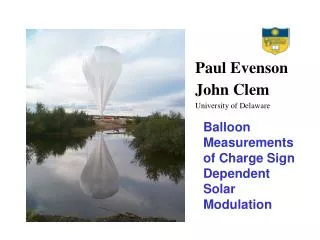
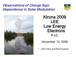
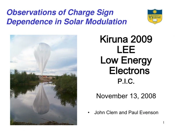
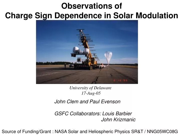
Observations of Charge Sign Dependence in Solar Modulation. University of Delaware 17-Aug-05. John Clem and Paul Evenson GSFC Collaborators: Louis Barbier John Krizmanic. Source of Funding/Grant : NASA Solar and Heliospheric Physics SR&T / NNG05WC08G.

E N D
Observations of Charge Sign Dependence in Solar Modulation University of Delaware 17-Aug-05 John Clem and Paul Evenson GSFC Collaborators: Louis Barbier John Krizmanic Source of Funding/Grant : NASA Solar and Heliospheric Physics SR&T / NNG05WC08G
Outline 1) Objectives 2) Instrument description 3) Flight Observations 4) Work area and Flight requirements 5) Current Status
AESOP Scientific Objectives To determine the extent to which the large scale structure of the heliospheric magnetic field is important in the propagation of charged cosmic ray particles in the heliosphere. To quantify this effect we intend to measure the time evolution of electron and positron particle fluxes spanning two solar cycles (22 years) 2
Every 11 years a solar cycle occurs based on sunspot numbers. During solar minimum particle fluxes are high and are low during solar max. As observed by Wilcox observatory, sun’s magnetic polarity reverses during solar max. A+ means magnetic north is located in Heliographical North
AESOP AESOP detects electrons with plastic scintillators T1, T3 and G (anticoincidence) and the gas Cherenkov detector T2. The instrument measures the electron energy in scintillator (T4) mounted below a 1cm lead disk and a leadglass (T5) calorimeter. Scintillator T6 also assists in particle identification and energy determination by counting the number of particles that escape the calorimeter. A permanent magnet hodoscope system determines the charge sign and momentum of the electron event. 25
Calorimeter Energy and Track Deflection measured during the 2002 AESOP flight. Electrons Positrons No Data cuts The vertical axis represents the energy measured in the Pb-Glass calorimeter while the horizontal represents the trajectory deflection in the magnet in units of inverse rigidity. 1GV corresponds to roughly 25milli-radians.The points are data recorded during the flight while the curves represents the ideal instrument response for positrons (positive side) and electrons (negative side).The red symbols represents those events tagged as high energy protons (E>20GeV to trigger gas CK) as determined by the T4 scintillator detector. The particle ID and energy of each event is assign using a likelyhood analysis 27
The world summary of positron abundance measurements as a function of energy for different epochs of solar magnetic polarity. Solid line is the local interstellar space abundance as calculated by Protheroe (1982). Dashed lines are from Clem et al. (1996) for A+ (top line) and A-. Solid symbols show data taken in the A+ state, while the open symbols represent data taken in the A- state. Consider only data at ~1.2GV….. The positron abundances in 2002 were quite low as expected during an A- solar maximum epoch. Only an upper limit could be determined in the 1.2 GeV energy bin As solar minimum approaches our flights should yield improved statistical accuracy.Nevertheless, these new observations support the results from the 2000 flight which revealed a significant decrease in the positron abundance from observations in the A+ polarity state. There is a suggestion that the abundance has decreased somewhat since 2000, but the statistical errors preclude a definitive statement. 29
Time profile of positron abundance (black) and anti-proton ratio (red) at a rigidity of roughly 1.2GV Solid symbols A+ state Open symbols A- state The black line is a positron abundance prediction based on the analysis of Clem et al. (1996). The red line is an antiproton/proton ratio drift model (Bieber et al. 1999). Dashed lines are the predicted results for future observations. The anti-protons were measured by the series of BESS flights (Asaoka et al. 2002) Observations from the 2000 and 2002 flight reveal a significant decrease in the cosmic-ray positron abundance at 1.2GV (black symbols) from a level that remained relatively stable throughout the decade of the 1990s. Even though the errors on this measurement are comparatively large due to the low particle fluxes at solar maximum, the magnitude of the effect is fairly consistent with the prediction of Clem et al. (1996). 30
Altitude is top Priority 1990s 2000s Estimated positron background (1.2GeV bin) for Solar min A- period as a function of depth
Using the NSBF balloon performance curves and Erich's weight estimation of NSBF's equipment for AESOP, the expected atmospheric background verses science weight can be determined. A theoretically 50light curve was included (red) purely based on volume displacement scaling of the 40L data. AESOP shell, instrument and gas bottle has been measured to ~950lbs..
During the 2002 flight, the AESOP-LEE flight accumulated over 10hrs above 135kft
AESOP flight requirements MinFloat Altitude: 2.6mbar (~135kft) MinFloat Duration: 10hrs Desired Float Altitude: 2.1mb (~140kft) Desired Float Duration: 75hrs (Altitude excursions are helpful) Flight Path should remain North of the 0.5GV geomagnetic cutoff
AESOP Instrument Flight Power Requirement: Heaters Off: 85watts Heaters On: 112watts (Data from Lynn Lake Flights reveal heaters are not needed for Conventional.) We intend to purchase a Flight-Ready Charge Controller from PSL. Our requirements are very similar to that of the SIP so it is expected we will acquire a system nearly identical that used by NSBF. AESOP Telemetry: Downlink: TDRSS high rate, LOS Uplink: TDRSS, LOS, 2 Discrete Lines (Power Control) Need data storage on SIP Reliable Fast Internet Service to OCC (Palestine)
The NSBF SIP Simulator has been an valuable tool for telemetry modification work for both uplink and downlink
GSE Setup: PC1:LOS Command/DAQ, Offline Analysis of Data transferred from PC5 during flight PC2:Remote Desktop to PC5 Backup Command PC3:Remote Desktop to PC4 Primary Command PC4:Remote Desktop Primary Server Command and DAQ PC5:Remote Desktop Server Backup Command and DAQ, Data transfer to PC1 PC6:Standalone DAQ (no internet connection, NSBF tape backup Local analysis)
Work Space Requirement 40x40ft work space 1ton overhead lift 5 x 115V power outlets 50amp Need 60hz converters for running motors Phone line Reliable internet service to OCC (Palestine)
Field Personnel: John Clem – Scientist Paul Evenson - Scientist Brian Lucas – Student Engineer Andrew McDermott – Sr. Tech James Roth - Tech Typically we require roughly 10 days of preparation time in Lynn Lake before declaring flight-ready, but working in a new location might require more time. Being the case, we will need a 2 week lead-time in Sweden.
Gas Bottles 4 x 90Ne/10He 65cft 1 x 90Ne/10He T size 3 x Nitrogen T sizeCommercial Grade Palestine: ( Can bottles be shipped from Palestine to Kiruna ? ) Kiruna: 6 x 90Ne/10He 65cft (4 for flight) 2 x 90Ne/10He T size 4 x Nitrogen T size Commercial Grade 2 x Helium T sizeCommercial Grade
American wood, Stay away from me We have been informed all wood items must be fumigated for insects before shipment.. Unfortunately all of our shipping crates are constructed with wood. What type of certification will be needed ??
Preliminary design of the AESOP platform: Currently working with NSBF personnel on the design and production on the Platform and PV array frame. The key issues are weight and mass in the viewing angle.
Modifications of the instrument should be completed late fall. Milestones: Telemetry Modifications: Sep-Oct Acquiring Solar Power System: ?? New Gondola Platform and Suspension: Oct Building shipping crates for the shells and instruments: Sept Wood Crate Fumigation: ??? (Certification shelf life ??) We expect to be in Palestine early January and ready for compatibility hanging early February. Tack själv