Download

1 / 84
840 likes | 965 Views
CMB Polarization Results from the Cosmic Background Imager. Steven T. Myers. National Radio Astronomy Observatory Socorro, NM. The Cosmic Background Imager. A collaboration between Caltech ( A.C.S. Readhead PI , S. Padin PS.) NRAO CITA Universidad de Chile University of Chicago

E N D
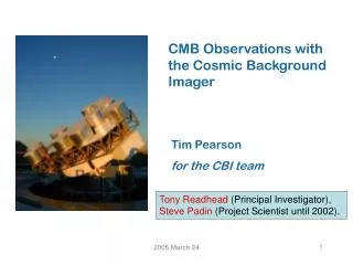
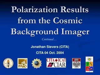
CMB Polarization Results from the Cosmic Background Imager Steven T. Myers National Radio Astronomy Observatory Socorro, NM
The Cosmic Background Imager • A collaboration between • Caltech (A.C.S. Readhead PI, S. Padin PS.) • NRAO • CITA • Universidad de Chile • University of Chicago • With participants also from • U.C. Berkeley, U. Alberta, ESO, IAP-Paris, NASA-MSFC, Universidad de Concepción • Funded by • National Science Foundation, the California Institute of Technology, Maxine and Ronald Linde, Cecil and Sally Drinkward, Barbara and Stanley Rawn Jr., the Kavli Institute, and the Canadian Institute for Advanced Research
The Cosmic Microwave Background • Discovered 1965 (Penzias & Wilson) • 2.7 K blackbody • Isotropic • Relic of hot “big bang” • 3 mK dipole (Doppler) • COBE 1992 • Blackbody 2.725 K • Anisotropies ≤10-5
The Expanding Universe • space is expanding with time • measured by scale factor a • or “redshift” z ~ inverse scale factor • a = 1 now; a = 0 at “Big Bang” • all linear scales (like wavelengths) expand as a • all else follows from this expansion! • radiation temperature T scales with 1/a • matter density 1/a3 ; radiation density 1/a4 • rate of expansion = H “Hubble constant” • controlled by matter and radiation density of Universe • H-1 “expansion time”, currently ~13 Gyr • expansion should be decelerating with time • accelerating !? “dark energy” with negative pressure! • speed of light c limits “horizon” of causality • isotropy of Universe suggests early phase of “inflation”
“Surface of last scattering” T≈3000°K z≈1000 THIS IS WHAT WE SEE AS THE CMB! Thermal History of the Universe “First 3 minutes”: very hot (10 million °K) like interior of Sun nucleosynthesis! Before “recombination”: hot (3000°K) like surface of Sun opaque, ionized plasma After “recombination”: cooler, transparent, neutral hydrogen gas Courtesy Wayne Hu – http://background.uchicago.edu
Matter History of the Universe • we see “structure” in Universe now • density fluctuations ~1 on 10 Mpc scales • clusters of galaxies! • must have been smaller in past (fluctuations grow) • in expanding Universe growth is approximately linear • CMB @ a = 0.001 density fluctuations ~ 0.001 • NOTE: density higher in past, but density fluctuations smaller! Courtesy Wayne Hu – http://background.uchicago.edu
Angular Power Spectrum • brightness fluctuations on surface of last scattering • due to the small (~0.1%) density variations • gravity causes flows (velocities) • radiation pressure resists compression bounces • acoustic waves! • Fourier analysis • break angular ripple pattern into sine & cosine • look for power on particular angular frequencies • like a cosmic Spectrum Analyzer! • acoustic waves + expansion fundamental + overtones • fundamental = scale of first compression since horizon crossing • scale set by sound crossing time at last scattering
CMB Acoustic Peaks • Compression driven by gravity, resisted by radiation ≈ “j ladder” series of harmonics + projection corrections peaks: ~ plsj troughs: ~ pls (j±½)
CMB Primary Anisotropies • Low l (<100) • primordial power spectrum (+ S-W, tensors, etc.) • Intermediate l (100-2000) • dominated by acoustic peak structure • position of peak related to sound crossing angular scale angular diameter distance to last scattering • peak heights controlled by baryons & dark matter, etc. • damping tail roll-off with • Large l (2000-5000+) • realm of the secondaries (e.g. SZE) Courtesy Wayne Hu – http://background.uchicago.edu
CMB Polarization • Due to quadrupolar intensity field at scattering NOTE: polarization maximum when velocity is maximum (out of phase with compression maxima) only transverse polarization can be transmitted on scattering! Courtesy Wayne Hu – http://background.uchicago.edu
CMB Polarization • E & B modes: translation invariance • E (even parity, “gradient”) • from scalar density fluctuations predominant! • B (odd parity, “curl”) • from gravity wave tensor modes, or secondaries Courtesy Wayne Hu – http://background.uchicago.edu
Note: polarization peaks out of phase w.r.t. intensity peaks Polarization Power Spectrum Planck “error boxes” Hu & Dodelson ARAA 2002
The Gold Standard: WMAP + “ext” WMAP ACBAR
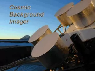
The Instrument • 13 90-cm Cassegrain antennas • 78 baselines • 6-meter platform • Baselines 1m – 5.51m • 10 1 GHz channels 26-36 GHz • HEMT amplifiers (NRAO) • Cryogenic 6K, Tsys 20 K • Single polarization (R or L) • Polarizers from U. Chicago • Analog correlators • 780 complex correlators • Field-of-view 44 arcmin • Image noise 4 mJy/bm 900s • Resolution 4.5 – 10 arcmin
CMB Interferometers • CMB issues: • Extremely low surface brightness fluctuations < 50 mK • Large monopole signal 3K, dipole 3 mK • Polarization less than 10% signal < 5 mK • No compact features, approximately Gaussian random field • Foregrounds both galactic & extragalactic • Traditional direct imaging • Differential horns or focal plane arrays • Interferometry • Inherent differencing (fringe pattern), filtered images • Works in spatial Fourier domain • Element-based errors vs. baseline-based signals • Limited by need to correlate pairs of elements • Sensitivity requires compact arrays
Traditional Inteferometer – The VLA • The Very Large Array (VLA) • 27 elements, 25m antennas, 74 MHz – 50 GHz (in bands) • independent elements Earth rotation synthesis
CMB Interferometer – The CBI • The Cosmic Background Imager (CBI) • 13 elements, 90 cm antennas, 26-36 GHz (10 channels) • fixed to 3-axis platform telescope rotation synthesis!
Other CMB Interferometers: DASI, VSA • DASI @ South Pole • VSA @ Tenerife
CBI milestones • 1980’s • 1984 OVRO 40m single-dish work (20 GHz maser Rx!) • 1987 genesis of idea for CMB interferometer • 1990’s • 1992 OVRO systems converted to HEMTs • 1994 NSF proposal (funded 1995) • 1998 assembled and tested at Caltech • 1999 August shipped to Chile • 1999 November Chile first “light” • 2000+ • 2000 January routine observing begins • 2001 first paper; 2002 first year results; 2003 2yrs; 2004 pol • 2002 continued NSF funding to end of 2004 • exploring funding prospects to operate until end of 2005
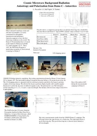
CBI Operations • Telescope at high site in Andes • 16000 ft (~5000 m) oxygen an issue! • Located on Science Preserve, co-located with ALMA • Now also ATSE (Japan) and APEX (Germany) • Future home of ACT, AT-25m, others? • Controlled on-site, oxygenated quarters in containers • Operations base in San Pedro de Atacama • population ~900 (but lots of tourists, and now astronomers!) • “low” elevation 8000 ft. (2500m) • about 1 ½ hours to site, good highway access
CBI Site – Northern Chilean Andes • Elevation 16500 ft.!
The CBI Adventure… • sunset
The CBI Adventure… • Steve Padin wearing the cannular oxygen system • because you never know when you need to dig the truck out!
The CBI Adventure… • the snow in Chile falls mainly on the road! 2 winters/yr
The CBI Adventure… • Volcan Lascar (~30 km away) erupts in 2001
The CMB and Interferometry • The sky can be uniquely described by spherical harmonics • CMB power spectra are described by multipole l • For small (sub-radian) scales the spherical harmonics can be approximated by Fourier modes • The conjugate variables are (u,v) as in radio interferometry • The uv radius is given by |u| =l / 2p • An interferometer naturally measures the transform of the sky intensity in l space convolved with aperture
multipole: l = 2pB/λ = 2p|uij| shortest CBI baseline: central hole 10cm The uv plane • The projected baseline length gives the angular scale
primary beam transform: θpri= 45' Δl ≈ 4D/λ ≈ 360 mosaic beam transform: θmos= n×45' Δl ≈ 4D/nλ CBI Beam and uv coverage • Over-sampled uv-plane • excellent PSF • allows fast gridded method (Myers et al. 2000)
Mosaicing in the uv plane offset & add phase gradients
Rohlfs & Wilson Polarization of radiation • Electromagnetic Waves • Maxwell: 2 independent linearly polarized waves • 3 parameters (E1,E2,d) polarization ellipse
The Poincare Sphere Rohlfs & Wilson Polarization of radiation • Electromagnetic Waves • Maxwell: 2 independent linearly polarized waves • 3 parameters (E1,E2,d) polarization ellipse • Stokes parameters (Poincare Sphere): • intensity I (Poynting flux) I2= E12 + E22 • linear polarization Q,U (mI)2= Q2 + U2 • circular polarization V (vI)2= V2
Polarization of radiation • Electromagnetic Waves • Maxwell: 2 independent linearly polarized waves • 3 parameters (E1,E2,d) polarization ellipse • Stokes parameters (Poincare Sphere): • intensity I (Poynting flux) I2= E12 + E22 • linear polarization Q,U (mI)2= Q2 + U2 • circular polarization V (vI)2= V2 • Coordinate system dependence: • I independent • V depends on choice of “handedness” • V > 0 for RCP • Q,U depend on choice of “North” (plus handedness) • Q “points” North, U 45 toward East • EVPA F = ½ tan-1 (U/Q) (North through East)
Polarization – Stokes parameters • CBI receivers can observe either RCP or LCP • cross-correlate RR, RL, LR, or LL from antenna pair • CMB intensity I plus linear polarization Q,U important • CMB not circularly polarized, ignore V (RR = LL = I) • parallel hands RR, LL measure intensity I • cross-hands RL, LR measure complex polarization P=Q+iU • R-L phase gives electric vector position angle F = ½ tan-1 (U/Q) • rotates with parallactic angle of detector y on sky
Polarization Interferometry • Parallel-hand & Cross-hand correlations • for antenna pair i, j and frequency channel n : • where kernel P is the aperture cross-correlation function • and y the baseline parallactic angle (w.r.t. deck angle 0°)
E and B modes • A useful decomposition of the polarization signal is into “gradient” and “curl modes” – E and B: E & B response smeared by phase variation over aperture A interferometer “directly” measures (Fourier transforms of) E & B!
Power Spectrum of CMB • Statistics of CMB field • Gaussian random field – Fourier modes independent • described by angular power spectrum • 4 non-zero polarization covariances: TT,EE,BB,TE • EB, TB should be zero due to parity (but check on systematics)
Errors: leakage • instrumental polarization • “leaks” L into R, R into L (level ~1%-2%) • e.g. Robs = R + d L • measure on bright source • use standard data analysis to determine d-terms • to first order: • TT unaffected • TT leaks into TE & TB • TE & TB leak into EE, BB, EB • include in correlation analysis • just complicates covariance matrix calculation
CBI Polarization New Results! astro-ph/0409569 (24 Sep 2004) Brought to you by: A. Readhead, T. Pearson, C. Dickinson (Caltech) S. Myers, B. Mason (NRAO), J. Sievers, C. Contaldi, J.R. Bond (CITA) P. Altamirano, R. Bustos, C. Achermann (Chile) & the CBI team!
CBI 2000+2001, WMAP, ACBAR, BIMA • Readhead et al. ApJ, 609, 498 (2004) • astro-ph/0402359 SZE Secondary CMB Primary
Carlstrom et al. 2003 astro-ph/0308478 2002 DASI & 2003 WMAP Polarization Courtesy Wayne Hu – http://background.uchicago.edu
New: DASI 3-year polarization results! • Leitch et al. 2004 (astro-ph/0409357) 16Sep04! • EE 6.3 σ • TE 2.9 σ • consistent w/ WMAP+ext model • BB consistent with zero • no foregrounds (yet)
CBI Current Polarization Data • Observing since Sep 2002 (processed to May 2004) • compact configuration, maximum sensitivity
CBI Polarization Upgrade • CBI instrumentation • Use quarter-wave devices for linear to circular conversion • Single amplifier per receiver: either R or L only per element • 2000 Observations • One antenna cross-polarized in 2000 (Cartwright thesis) • Only 12 cross-polarized baselines (cf. 66 parallel hand) • Original polarizers had 5%-15% leakage • Deep fields, upper limit ~8 mK • 2002 Upgrade • Upgrade in 2002 using DASI polarizers (J. Kovac) • Observing with 7R + 6L starting Sep 2002 • Raster scans for mosaicing and efficiency • New TRW InP HEMTs from NRAO
Calibration from WMAP Jupiter • Old uncertainty: 5% • 2.7% high vs. WMAP Jupiter • New uncertainty: 1.3% • Ultimate goal: 0.5%