Download
1 / 21
210 likes | 304 Views
VV Support Fixture FPA Stage 1. PDR Review August 10, 2005. T. Brown. Component Installation Fixture Design Requirements.

E N D
VV Support FixtureFPA Stage 1 PDR Review August 10, 2005 T. Brown
Component Installation FixtureDesign Requirements The installation fixture shall provide a cost-effective (economical) system to install the magnetic loops, VV heating tubes and I&C components while meeting individual installation requirements. • heating tubes are not expected to impose any specific requirements on their vessel installation fixture other then requiring accessibility to comfortably assemble and attach the tubes. • The magnetic loops need to be installed and their final position accurately measured. The vessel surface deflection should be far smaller than other sources of deflection. • The Rogowski coil that initially was to be installed on the VV has been moved to the MC shell.
Diagnostic Loop Arrangement ~ 70 loops will be placed on each vessel field period Location marks to place the loops “may be” done by MTM otherwise we will need to use the Roamer Arm or Leica to provide the locating marks.
Heating Tube Arrangement 64 tubes with 600 studs at ~8” spacing will be placed on each vessel field period
Component Weights (lbs) • Vacuum Vessel – 3,629 • Heating tubes – 1,000 • Magnetic loops – 100 • I & C – 25 4,754 lbs
10 ½ ‘ 13 ½ ‘ Basic Dimensions Shell Fabrication profile tolerance is 3/8” and ports are welded on after loops are installed.
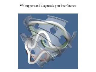
Parting Flange Position Vertical Position NB Flange Position Alternate Support Arrangements
Vacuum Vessel displacement contours for atmospheric + gravity loads
Selected Design Approach Supporting the vacuum vessel using a vertical port trunnion support scheme is the most cost-effective approach that allows comfortable access to the vessel surface. For this arrangement the vessel surface deflection should be far smaller than other sources of deflection. Therefore, my recommended is that the trunnion support system be adopted.
Simple support stands are bolted to the floor. The VV is supported off existing vertical port blank-off flanges with a bolt on end tube. Hold down plat used to fix the VV position Hoist ring attachment at each end for crane access.
The vessel support stand is expected to be fabricated in house. The bill of material is listed on the dawning.
Support Stand Analysis max_disp_mag: 2.498132e-05 max_disp_x: 2.263886e-06 max_disp_y: -2.463176e-05 max_disp_z: 4.342628e-06 max_prin_mag: -2.881519e+04 max_rot_mag: 2.418002e-06 max_rot_x: -2.143861e-06 max_rot_y: 2.417384e-06 max_rot_z: 9.094709e-07 max_stress_prin: 8.007318e+03 max_stress_vm: 2.863659e+04 max_stress_xx: -1.089471e+04 max_stress_xy: -5.533265e+03 max_stress_xz: -2.562494e+03 max_stress_yy: -2.860049e+04 max_stress_yz: 7.052411e+03 max_stress_zz: -1.110182e+04 min_stress_prin: -2.881519e+04 strain_energy: 1.597775e-01 ASTM A36 Carbon Steel Fty = 36 ksi Ftu = 58 ksi
Charge: • Are the requirements well defined? • Does the design adequately address the requirements? • Does the analysis adequately underpin the design? • Do the drawings define the design adequately to be used as the sole basis for fabrication and acceptance of the support fixture? • Has safety been adequately addressed in the design of the support fixture? • Can the support fixture be fabricated and installed within the budget and schedule identified in the project baseline? • What additional work or documentation should be done in order to complete the final design?