Download
1 / 15

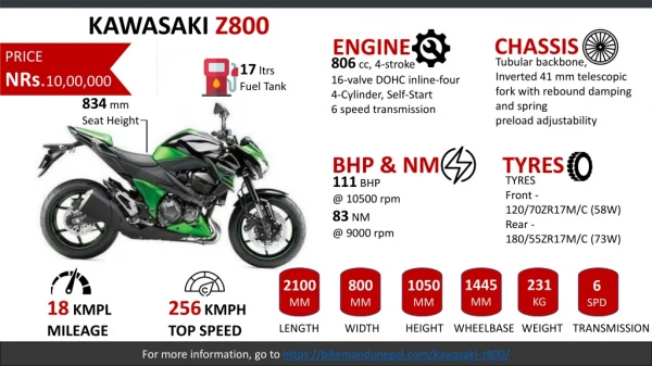
E N D
Quick Reference Guide General Information 1 j Fuel System 2 j Cooling System 3 j Engine Top End 4 j Clutch 5 j Engine Lubrication System 6 j Engine Removal/Installation 7 j Crankshaft/Transmission 8 j Wheels/Tires 9 j Final Drive 10 j Brakes 11 j Suspension 12 j Steering 13 j Frame 14 j Electrical System 15 j Appendix 16 j This quick reference guide will assist you in locating a desired topic or pro- cedure. •Bend the pages back to match the black tab of the desired chapter num- ber with the black tab on the edge at each table of contents page. •Refer to the sectional table of contents for the exact pages to locate the spe- cific topic required.
ER-5 Motorcycle Service Manual All rights reserved. No parts of this publication may be reproduced, stored in a retrieval system, or transmitted in any form or by any means, electronic mechanical photocopying, recording or otherwise, without the prior written permission of Quality Assurance Department/Consumer Products & Machinery Company/Kawasaki Heavy Industries, Ltd., Japan. No liability can be accepted for any inaccuracies or omissions in this publication, although every possible care has been taken to make it as complete and accurate as possible. The right is reserved to make changes at any time without prior notice and without incurring an obligation to make such changes to products manufactured previously. See your Motorcycle dealer for the latest information on product improvements incorporated after this publication. All information contained in this publication is based on the latest product information available at the time of publication. Illustrations and photographs in this publication are intended for reference use only and may not depict actual model component parts. © 2000 Kawasaki Heavy Industries, Ltd. 4th Edition (1): Aug. 5, 2004 (K)
LIST OF ABBREVIATIONS A ABDC AC ATDC BBDC BDC BTDC °C DC F °F ft g h L ampere(s) after bottom dead center alternating current after top dead center before bottom dead center bottom dead center before top dead center degree(s) Celsius direct current farad(s) degree(s) Fahrenheit foot, feet gram(s) hour(s) liter(s) lb m min N Pa PS psi r rpm TDC TIR V W Ω pound(s) meter(s) minute(s) newton(s) pascal(s) horsepower pound(s) per square inch revolution revolution(s) per minute top dead center total indicator reading volt(s) watt(s) ohm(s) Read OWNER’S MANUAL before operating.
EMISSION CONTROL INFORMATION To protect the environment in which we all live, Kawasaki has incorporated crankcase emis- sion (1) and exhaust emission (2) control systems in compliance with applicable regulations of the United States Environmental Protection Agency and California Air Resources Board. Addi- tionally, Kawasaki has incorporated an evaporative emission control system (3) in compliance with applicable regulations of the California Air Resources Board on vehicles sold in California only. 1. Crankcase Emission Control System Thissystem eliminates the release ofcrankcase vapors into the atmosphere. Instead, the vapors are routed through an oil separator to the intake side of the engine. While the engine is operating, the vapors are drawn into combustion chamber, where they are burned along with the fuel and air supplied by the carburetion system. 2. Exhaust Emission Control System This system reduces the amount of pollutants discharged into the atmosphere by the exhaust of this motorcycle. The fuel, ignition, and exhaust systems of this motorcycle have been carefully designed and constructed to ensure an efficient engine with low exhaust pollutant levels. 3. Evaporative Emission Control System Vapors caused by fuel evaporation in the fuel system are not vented into the atmosphere. In- stead, fuel vapors are routed into the running engine to be burned, or stored in a canister when the engine is stopped. Liquid fuel is caught by a vapor separator and returned to the fuel tank. The Clean Air Act, which is the Federal law covering motor vehicle pollution, contains what is commonly referred to as the Act’s "tampering provisions." "Sec. 203(a) The following acts and the causing thereof are prohibited... (3)(A) for any person to remove or render inoperative any device or element of design installed on or in a motor vehicle or motor vehicle engine in compliance with regulations under this title prior to its sale and delivery to the ultimate purchaser, or for any manufacturer or dealer knowingly to remove or render inoperative any such device or element of design after such sale and delivery to the ultimate purchaser. (3)(B) for any person engaged in the business of repairing, servicing, selling, leasing, or trading motor vehicles or motor vehicle engines, or who operates a fleet of motor vehicles know- ingly to remove or render inoperative any device or element of design installed on or in a motor vehicle or motor vehicle engine in compliance with regulations under this title follow- ing its sale and delivery to the ultimate purchaser..." NOTE ○The phrase "remove or render inoperative any device or element of design" has been generally interpreted as follows: 1. Tampering does not include the temporary removal or rendering inoperative of de- vices or elements of design in order to perform maintenance. 2. Tampering could include: a.Maladjustment of vehicle components such that the emission standards are ex- ceeded. b.Use of replacement parts or accessories which adversely affect the performance or durability of the motorcycle. c.Addition of components or accessories that result in the vehicle exceeding the stan- dards. d.Permanently removing, disconnecting, or rendering inoperative any component or element of design of the emission control systems. WE RECOMMEND THAT ALL DEALERS OBSERVE THESE PROVISIONS OF FEDERAL LAW, THE VIOLATION OF WHICH IS PUNISHABLE BY CIVIL PENALTIES NOT EXCEEDING $10,000 PER VIOLATION.
TAMPERING WITH NOISE CONTROL SYSTEM PROHIBITED Federal law prohibits the following acts or the causing thereof: (1) The removal or rendering inoperative by any person other than for purposes of maintenance, repair, or replacement, of any device or element of design incorporated into any new vehicle for the purpose of noise control prior to its sale or delivery to the ultimate purchaser or while it is in use, or (2) the use of the vehicle after such device or element of design has been removed or rendered inoperative by any person. Among those acts presumed to constitute tampering are the acts listed below: •Replacement of the original exhaust system or muffler with a component not in compliance with Federal regulations. •Removal of the muffler(s) or any internal portion of the muffler(s). •Removal of the air box or air box cover. •Modifications to the muffler(s) or air intake system by cutting, drilling, or other means if such modifications result in increased noise levels.
Foreword This manual is designed primarily for use by trained mechanics in a properly equipped shop. However, it contains enough detail and basic in- formation to make it useful to the owner who de- sires to perform his own basic maintenance and repair work. A basic knowledge of mechanics, the proper use of tools, and workshop proce- dures must be understood in order to carry out maintenance and repair satisfactorily. When- ever the owner has insufficient experience or doubts his ability to do the work, all adjust- ments, maintenance, and repair should be car- ried out only by qualified mechanics. In order to perform the work efficiently and to avoid costly mistakes, read the text, thor- oughly familiarize yourself with the procedures before starting work, and then do the work care- fully in a clean area. Whenever special tools or equipment are specified, do not use makeshift tools or equipment. Precision measurements can only be made if the proper instruments are used, and the use of substitute tools may ad- versely affect safe operation. For the duration of the warranty period, we recommend that all repairs and scheduled maintenance be performed in accordance with thisservice manual. Any owner maintenance or repair procedure not performed in accordance with this manual may void the warranty. To get the longest life out of your vehicle: •Follow the Periodic Maintenance Chart in the Service Manual. •Be alert for problems and non-scheduled maintenance. •Use proper tools and genuine Kawasaki Mo- torcycle parts. Special tools, gauges, and testers that are necessary when servicing Kawasaki motorcycles are introduced by the Special Tool Catalog or Manual. parts provided as spare parts are listed in the Parts Catalog. •Follow the procedures in this manual care- fully. Don’t take shortcuts. •Remembertokeepcompleterecordsofmain- tenance and repair with dates and any new parts installed. The Quick Reference Guide shows you all of the product’s system and assists in locating their chapters. Each chapter in turn has its own comprehensive Table of Contents. For example, if you want ignition coil informa- tion, use the Quick Reference Guide to locate the Electrical System chapter. Then, use the Table of Contents on the first page of the chap- ter to find the ignition coil section. Whenever you see these WARNING and CAUTION symbols, heed their instructions! Always follow safe operating and maintenance practices. WARNING This warning symbol identifies special instructions or procedures which, if not correctly followed, could result in per- sonal injury, or loss of life. CAUTION This caution symbol identifies special instructions or procedures which, if not strictly observed, could result in dam- age to or destruction of equipment. This manual contains four more symbols (in additiontoWARNINGandCAUTION)whichwill help you distinguish different types of informa- tion. NOTE ○This note symbol indicates points of par- ticular interest for more efficient and con- venient operation. •Indicates a procedural step or work to be done. ○Indicates a procedural sub-step or how to do the work of the procedural step it follows. It also precedes the text of a NOTE. Indicates a conditional step or what action to take based on the results of the test or inspec- tion in the procedural step or sub-step it fol- lows. In most chapters an exploded view illustration of the system components follows the Table of Contents. In these illustrations you will find the instructions indicating which parts require spec- ified tightening torque, oil, grease or a locking agent during assembly. Genuine How to Use This Manual In this manual, the product is divided into its major systems and these systems make up the manual’s chapters.
GENERAL INFORMATION 1-1 General Information 1 Table of Contents Before Servicing..................................................................................................................... Model Identification................................................................................................................. General Specifications............................................................................................................ Periodic Maintenance Chart................................................................................................... Torque and Locking Agent...................................................................................................... Special Tools and Sealants .................................................................................................... Cable, Wire, and Hose Routing.............................................................................................. 1-2 1-5 1-6 1-9 1-11 1-16 1-23
1-2 GENERAL INFORMATION Before Servicing Before starting to perform an inspection service or carry out a disassembly and reassembly opera- tion on a motorcycle, read the precautions given below. To facilitate actual operations, notes, illustra- tions, photographs, cautions, and detailed descriptions have been included in each chapter wherever necessary. This section explains the items that require particular attention during the removal and reinstallation or disassembly and reassembly of general parts. Especially note the following: (1) Dirt Before removal and disassembly, clean the motorcycle. Any dirt entering the engine will shorten the life of the motorcycle. For the same reason, before installing a new part, clean off any dust or metal filings. (2) Battery Ground Disconnect the ground (–) wire from the battery before performing any disassembly operations on the motorcycle. This prevents the engine from accidentally turning over while work is being carried out, sparks from being generated while disconnecting the wires from electrical parts, as well as damage to the electrical parts themselves. For reinstallation, first connect the positive wire to the positive (+) terminal of the battery (3) Installation, Assembly Generally, installation or assembly is the reverse of removal or disassembly. However, if instal- lation or assembly sequence is given in this Service Manual, follow it. Note parts locations and cable, wire, and hose routing during removal or disassembly so they can be installed or assem- bled in the same way. It is preferable to mark and record the locations and routing whenever possible. (4) Tightening Sequence When installing bolts, nuts, or screws for which a tightening sequence is given in this Service Manual, make sure to follow the sequence. When installing a part with several bolts, nuts, or screws, start them all in their holes and tighten them to a snug fit, thus ensuring that the part has been installed in its proper location. Then, tighten them to the specified torque in the tightening sequence and method indicated. If tightening sequence instructions are not given, tighten them evenly in a cross pattern. Conversely, to remove a part, first loosen all the bolts, nuts, or screws that are retaining the part a 1/4-turn before removing them. (5) Torque When torque values are given in this Service Manual, use them. Either too little or too much torque may lead to serious damage. Use a good quality, reliable torque wrench. (6) Force Common sense should dictate how much force is necessary in assembly and disassembly. If a part seems especially difficult to remove or install, stop and examine what may be causing the problem. Whenever tapping is necessary, tap lightly using a wooden or plastic-faced mallet. Use an impact driver for screws (particularly for the removing screws held by non-permanent locking agent) in order to avoid damaging the screw heads. (7) Edges Watch for sharp edges, as they could cause injury through careless handling, especially during major engine disassembly and assembly. Use a clean piece of thick cloth when lifting the engine or turning it over. (8) High-Flash Point Solvent A high-flash point solvent is recommended to reduce fire danger. A commercial solvent com- monly available in North America is standard solvent (generic name). Always follow manufacturer and container directions regarding the use of any solvent. (9) Gasket, O-ring Replace a gasket or an O-ring with a new part when disassembling. Remove any foreign matter from the mating surface of the gasket or O-ring to ensure a perfectly smooth surface to prevent oil or compression leaks.
GENERAL INFORMATION 1-3 Before Servicing (10)Liquid Gasket, Locking Agent Clean and prepare surfaces where liquid gasket or non-permanent locking agent will be used. Apply them sparingly. Excessive amount may block engine oil passages and cause serious dam- age. (11)Press When using a press or driver to install a part such as a wheel bearing, apply a small amount of oil to the area where the two parts come in contact to ensure a smooth fit. (12)Ball Bearing and Needle Bearing Do not remove a ball bearing or a needle bearing unless it is absolutely necessary. Replace any ball or needle bearings that were removed with new ones. Install bearings with the manufacturer and size marks facing out, applying pressure evenly with a suitable driver. Apply force only to the end of the race that contacts the press fit portion, and press it evenly over the base component. (13)Oil Seal and Grease Seal Replace any oil or grease seals that were removed with new ones, as removal generally dam- ages seals. Oil or grease seals should be pressed into place using a suitable driver, applying a force uniformly to the end of seal until the face of the seal is even with the end of the hole, unless instructed otherwise. When pressing in an oil or grease seal which has manufacturer’s marks, press it in with the marks facing out. (14)Circlip, Retaining Ring, and Cotter Pin When installing circlips and retaining rings, take care to compress or expand them only enough to install them and no more. Install the circlip with its chamfered side facing load side as well. Replace any circlips, retaining rings, and cotter pins that were removed with new ones, as re- moval weakens and deforms them. If old ones are reused, they could become detached while the motorcycle is driven, leading to a major problem. (15)Lubrication Engine wear is generally at its maximum while the engine iswarming up and before allthe sliding surfaces have an adequate lubricative film. During assembly, make sure to apply oil to any sliding surface or bearing that has been cleaned. Old grease or dirty oil could have lost its lubricative quality and may contain foreign particles that act as abrasives; therefore, make sure to wipe it off and apply fresh grease or oil. Some oils and greases in particular should be used only in certain applications and may be harmful if used in an application for which they are not intended. (16)Direction of Engine Rotation To rotate the crankshaft manually, make sure to do so in the direction of positive rotation. Pos- itive rotation is counterclockwise as viewed from the left side of the engine. To carry out proper adjustment, it is furthermore necessary to rotate the engine in the direction of positive rotation as well. (17)Replacement Parts When there is a replacement instruction, replace these parts with new ones every time they are removed. Replacementpartswillbedamagedorlosetheiroriginalfunctiononcetheyareremoved. There- fore, always replace these parts with new ones every time they are removed. Although the pre- viously mentioned gasket, O-ring, ball bearing, needle bearing, grease seal, oil seal, circlip, and cotter pin have not been so designated in their respective text, they are replacement parts. (18)Electrical Wires All the electrical wires are either one-color or two-color. A two-color wire is identified first by the primary color and then the stripe color. For example, a yellow wire with thin red stripes is referred to as a “yellow/red” wire; it would be a “red/yellow” wire if the colors were reversed. Unless in- structed otherwise, electrical wires must be connected to wires of the same color.
1-4 GENERAL INFORMATION Before Servicing Two-Color Electrical (19)Inspection When parts have been disassembled, visually inspect these parts for the following conditions or other damage. If there is any doubt as to the condition of them, replace them with new ones. Abrasion Bent Color change Crack Dent Deterioration Hardening Scratch Seizure Warp Wear (20)Specifications Specification terms are defined as follows: "Standards" show dimensions or performances which brand-new parts or systems have. "Service Limits" indicate the usable limits. If the measurement shows excessive wear or dete- riorated performance, replace the damaged parts.
Thank you very much for your reading. Please Click Here. Then Get COMPLETE MANUAL. NO WAITING NOTE: If there is no response to click on the link above, please download the PDF document first and then click on it.
GENERAL INFORMATION 1-5 Model Identification ER500-C1, D1 Left Side View ER500-C1, D1 Right Side View
1-6 GENERAL INFORMATION General Specifications EN500-C1 ∼ ∼ C2 EN500-C3 ∼ ∼ Items EN500-D1 Dimensions Overall Length Overall Width Overall Height Wheelbase Road Clearance Seat Height Dry Weight Curb Weight: Front Rear Fuel tank Capacity Performance Minimum Turning Radius Engine Type Cooling System Bore and Stroke Displacement Compression Ratio Maximum Horsepower 2 070 mm (81.5 in.) 730 mm (28.74 in.) 1 070 mm (42.13 in.) 1 430 mm (56.3 in.) 125 mm (4.92 in.) 800 mm (31.5 in.) 179 kg (395 lb.) ← ← ← ← ← ← ← ← ← ← ← ← ← ← 92 kg (203 lb.) 107 kg (236 lb.) 17 L (4.5 US gal.) ← ← ← ← ← ← 2.5 m (8.2 ft.) ← ← 4-stroke, DOHC, 2-cylinder Liquid-cooled 74.0 × 58.0 mm (2.91 × 2.28 in.) 498 mL (30.39 cu in.) 9.8:1 37 kW (50.3 PS) @9 000 r/min (rpm) ← ← ← ← ← ← ← ← ← ← ← 25 kW (34 PS) @8 000 r/min (rpm) 37 N·m (3.8 kgf·m, 27 ft·lb) @4 500 r/min (rpm) ← ← ← ← ← Maximum Torque 45 N·m (4.6 kgf·m, 33 ft·lb) @7 200 r/min (rpm) ← Carburetion System Starting System Ignition System Timing Advance Ignition Timing Carburetors, Keihin CVK34 × 2 Electric starter Battery and coil (transistorized) Electronically Advanced (digital) From 10° BTDC @1 200 r/min (rpm) to 37.5° BTDC @10 000 r/min (rpm) NGK DR9EA or ND X27ESR-U ← ← ← ← ← Spark Plugs Cylinder Numbering Method Left to right, 1-2 Firing Order Valve Timing: Inlet Open Close DuRation Exhaust Open Close DuRation ← ← ← ← ← ← 1-2 31° BTDC 51° ABDC 262° ← ← ← ← ← ← 56° BBDC 26° ATDC 262° ← ← ← ← ← ←
GENERAL INFORMATION 1-7 General Specifications EN500-C1 ∼ ∼ C2 EN500-C3 ∼ ∼ ← Items EN500-D1 ← Lubrication System Engine Oil: Grade Forced lubrication API SE, SF, SG or API SH or SJ with JASO MA SAE10W-40 3.4 L (3.6 us at) ← ← Viscosity Capacity Drive Train Primary Reduction System: Type Reduction Ratio Clutch Type Transmission: Type Gear Ratios: 1st 2nd 3rd 4th 5th 6th Final Drive System: Type Reduction Ratio Overall Drive Ratio Frame Type Caster (rake angle) Trail Front Tire: Type Size ← ← ← ← Chain 2.652 (61/23) Wet multi disc ← ← ← ← ← ← 6-speed constant mesh, return shift ← ← 2.571 (36/14) 1.722 (31/18) 1.333 (28/21) 1.125 (27/24) 0.961 (25/26) 0.851 (23/27) ← ← ← ← ← ← ← ← ← ← ← ← Chain drive 2.470 (42/17) 5.581 @Top gear ← ← ← ← ← ← Tubular, double cradle 27° 102 mm (4.02 in.) ← ← ← ← ← ← Tubeless 110/70-17 54H ← ← 110/70-17 M/C 54H 110/70-17 54H Rear Tire: Type Size Tubeless 130/70-17 62H ← ← 130/70-17 M/C 62H 130/70-17 62H Front Suspension: Type Wheel Travel Rear Suspension: Type Wheel Travel Brake Type: Front Rear Telescopic fork 125 mm (4.92 in.) ← ← ← ← Swingarm 114 mm (4.49 in.) ← ← ← ← Single disc Drum ← ← ← ←