Download
1 / 21
210 likes | 218 Views
New Holland TN95VA Tractor Service Repair Manual

E N D
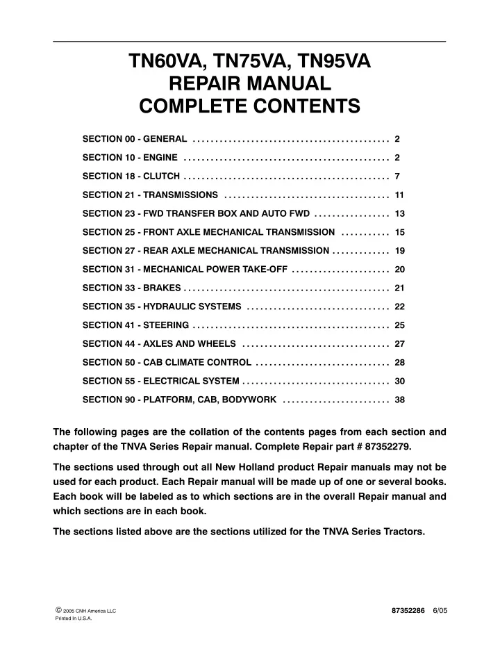
TN60VA, TN75VA, TN95VA REPAIR MANUAL COMPLETE CONTENTS SECTION 00 - GENERAL . . . . . . . . . . . . . . . . . . . . . . . . . . . . . . . . . . . . . . . . . . . . 2 SECTION 10 - ENGINE . . . . . . . . . . . . . . . . . . . . . . . . . . . . . . . . . . . . . . . . . . . . . . 2 SECTION 18 - CLUTCH . . . . . . . . . . . . . . . . . . . . . . . . . . . . . . . . . . . . . . . . . . . . . . 7 SECTION 21 - TRANSMISSIONS . . . . . . . . . . . . . . . . . . . . . . . . . . . . . . . . . . . . . 11 SECTION 23 - FWD TRANSFER BOX AND AUTO FWD . . . . . . . . . . . . . . . . . 13 SECTION 25 - FRONT AXLE MECHANICAL TRANSMISSION . . . . . . . . . . . 15 SECTION 27 - REAR AXLE MECHANICAL TRANSMISSION . . . . . . . . . . . . . 19 SECTION 31 - MECHANICAL POWER TAKE-OFF . . . . . . . . . . . . . . . . . . . . . . 20 SECTION 33 - BRAKES . . . . . . . . . . . . . . . . . . . . . . . . . . . . . . . . . . . . . . . . . . . . . . 21 SECTION 35 - HYDRAULIC SYSTEMS . . . . . . . . . . . . . . . . . . . . . . . . . . . . . . . . 22 SECTION 41 - STEERING . . . . . . . . . . . . . . . . . . . . . . . . . . . . . . . . . . . . . . . . . . . . 25 SECTION 44 - AXLES AND WHEELS . . . . . . . . . . . . . . . . . . . . . . . . . . . . . . . . . 27 SECTION 50 - CAB CLIMATE CONTROL . . . . . . . . . . . . . . . . . . . . . . . . . . . . . . 28 SECTION 55 - ELECTRICAL SYSTEM . . . . . . . . . . . . . . . . . . . . . . . . . . . . . . . . . 30 SECTION 90 - PLATFORM, CAB, BODYWORK . . . . . . . . . . . . . . . . . . . . . . . . 38 The following pages are the collation of the contents pages from each section and chapter of the TNVA Series Repair manual. Complete Repair part # 87352279. The sections used through out all New Holland product Repair manuals may not be used for each product. Each Repair manual will be made up of one or several books. Each book will be labeled as to which sections are in the overall Repair manual and which sections are in each book. The sections listed above are the sections utilized for the TNVA Series Tractors. 87352286 6/05 © 2005 CNH America LLC Printed In U.S.A.
SECTION 00 - - GENERAL - - CHAPTER 1 SECTION 00 - GENERAL Chapter 1 - General CONTENTS Section Description Page General Instructions . . . . . . . . . . . . . . . . . . . . . . . . . . . . . . . . . . . . . . . . . . . . . . . . . . . . . . . . . . . . 3 Health and Safety . . . . . . . . . . . . . . . . . . . . . . . . . . . . . . . . . . . . . . . . . . . . . . . . . . . . . . . . . . . . . . 5 Precautionary Statements . . . . . . . . . . . . . . . . . . . . . . . . . . . . . . . . . . . . . . . . . . . . . . . . . . . . . 15 Safety . . . . . . . . . . . . . . . . . . . . . . . . . . . . . . . . . . . . . . . . . . . . . . . . . . . . . . . . . . . . . . . . . . . . . . 16 Ecology and the Environment . . . . . . . . . . . . . . . . . . . . . . . . . . . . . . . . . . . . . . . . . . . . . . . . . . 19 Minimum Hardware Tightening Torques . . . . . . . . . . . . . . . . . . . . . . . . . . . . . . . . . . . . . . . . . 20 Federal Emissions Warranty . . . . . . . . . . . . . . . . . . . . . . . . . . . . . . . . . . . . . . . . . . . . . . . . . . . 22 Consumables . . . . . . . . . . . . . . . . . . . . . . . . . . . . . . . . . . . . . . . . . . . . . . . . . . . . . . . . . . . . . . . . 25 00-1
SECTION 00 - - GENERAL - - CHAPTER 1 SAFETY PRECAUTIONARY STATEMENTS A careful operator is the best operator. Most accidents can be avoided by observing certain precautions. To help prevent accidents, read the following precautions before operating this equipment. Equipment should be operated only by those who are responsible and instructed to do so. Carefullyreviewtheproceduresgiveninthismanualwithalloperators.Itisimportantthatalloperatorsbefamiliar with and follow safety precautions. THE TRACTOR 5. Use extreme caution and avoid hard application of the tractor brakes when towing heavy loads at road speeds. 1. Read the Operator’s Manual carefully before using the tractor. Lack of operating knowledge can lead to accidents. 6. Any towed vehicle whose total weight exceeds that of the towing tractor must be equipped with brakes for safe operation. 2. Onlyallowproperlytrainedandqualifiedpersons to operate the tractor. 7. Never apply the differential lock when turning. When engaged, the differential lock will prevent the tractor from turning. 3. Topreventfalls,usethehandrailsandstepplates when getting on and off the tractor. Keep steps and platform clear of mud and debris. 8. Always check overhead clearance, specifically when transporting the tractor. Watch where you are going, especially obstacles. 4. Do not permit anyone but the operator to ride on the tractor unless a passenger seat is fitted. There is no safe place for extra riders otherwise. at low overhanging 5. Replace all missing, illegible or damaged safety decals. 9. Use extreme caution when operating on steep slopes. 6. Keep safety decals free of dirt or grime. 10. Toavoidoverturns,drivethetractorwithcareand at speeds compatible with safety, especially when operating over rough ground, when crossing ditches or slopes and when turning overturning. 7. Do not modify or alter or permit anyone else to modify or alter the tractor or any of its components or any tractor function without first consulting your dealer. 11. Ifthetractorbecomesstuckorthetiresarefrozen to the ground, reverse the tractor out to prevent corners. 8. Tractor wheels are very heavy. Handle with care and ensure, when stored, that they cannot fall. DRIVING THE TRACTOR 12. Keep the tractor in the same gear when going downhill as would be used when going uphill. Do not coast or freewheel down hills. 1. Always sit in the drivers seat while starting or driving the tractor. 2. When driving on public roads, have considera- tion for other road users. Pull in to the side of the road occasionally to allow any following traffic to pass. Do not exceed the legal speed limit set in your area. OPERATING THE TRACTOR 1. Applytheparkingbrake,placethePTOcontrolin the ‘OFF’ position, the lift control lever in the down position, the remote control valve levers in the neutral position and the transmission lever in neutral before starting the tractor. 3. Use low beam lights when meeting a vehicle at night. Make sure the lights are adjusted to preventblindingthedrive ofan oncomingvehicle 2. Do not start the engine or operate controls while standing beside the tractor. Always sit in the tractorseatwhenstartingtheengineoroperating the controls. 4. Reduce speed before turning or applying the brakes.Ensurethatbothbrakepedalsarelocked together when traveling at road speeds or when on public roads. Brake both wheels simulta- neously when making an emergency stop. 00-16
SECTION 00 - - GENERAL - - CHAPTER 1 a hazard both to the operator and to bystanders. Do not overload or operate with attached equipment which is unsafe, not designed for the particular task or is poorly maintained. 3. Donotbypasstheneutralstartswitches.Consult your authorized dealer if your neutral start controlsmalfunction.Usejumpcablesonly inthe recommended manner. Improper use can result in a tractor runaway. 19. The tractor is designed to provide the minimum noise level at the operator’s ears and meets or exceeds applicable standards in this respect. However, noise (sound pressure level) in the workplace can exceed 86 dB(A) when working between buildings or in Therefore, it is recommended that operators wear suitable ear protectors during vehicle operation. 4. Avoidaccidentalcontactwiththegearshiftlevers while the engine is running. Unexpected tractor movement can result from such contact. 5. Do not get off the tractor while it is in motion. confined spaces. 6. Shut off the engine and PTO and apply the parking brake before getting off the tractor. 7. Do not park the tractor on a steep incline. OPERATING THE PTO 8. Do not run the tractor engine in an enclosed building without adequate ventilation. Exhaust fumes are toxic and can cause death. 1. When operating PTO driven equipment, shut off the engine and wait until the PTO stops before getting off the tractor and disconnecting the equipment. 9. Always wear a protective mask when working with toxic spray chemicals. Follow the directions on the chemical container. 2. Do not wear loose clothing when operating the power take-off or especially when near rotating equipment. 10. Ifthepowersteeringorengineceasesoperating, stop the tractor immediately as the tractor will be more difficult to control. 3. When operating stationary PTO driven equip- ment, always apply the tractor parking brake and block the rear wheels front and back. 11. Stop the engine and relieve pressure before connecting or disconnecting hydraulic, steering or fuel lines. 4. To avoid injury, do not clean, adjust, unclog or service PTO driven equipment when the tractor engine is running. 12. Tighten all connections before starting the engine or pressurizing lines. 5. Make sure the PTO guard is in position at all times and always replace the PTO cap when the PTO is not in use. 13. Pull only from the swinging drawbar or the lower link drawbar in the lowered position . Use only a drawbar pin that locks in place. Pulling from the tractor rear axle or any point above the axle may cause the tractor to overturn. SERVICING THE TRACTOR 1. The cooling system operates under pressure which is controlled by the radiator cap. It is dangerous to remove the cap whilethe systemis hot. Always turn the cap slowly to the first stop and allow the pressure to escape before removing the cap entirely. 14. If the front end of the tractor tends to rise when heavy implements are attached to the three- point hitch, install front end or front wheel weights. Do not operate the tractor with a light front end. 15. Always select Position Control when attaching implements and when transporting equipment. Be sure hydraulic couplers are properly installed and will disconnect safety in case of accidental detachment of the implement. 2. Do not smoke while refueling the tractor. Keep any type of open flame away. Wait for the engine to cool before refueling. 3. Keep the tractor and equipment, particularly brakes and steering, maintained in a reliable and satisfactory condition to ensure your safety and comply with legal requirements. 16. Do not leave equipment in the raised position when the vehicle is stopped or unattended. 17. Ensure any attached equipment or accessories are correctly installed, are approved for use with the tractor, do not overload the tractor and are operated and maintained in accordance with the instructions issued accessory manufacturer. 4. To prevent fire or explosion, keep open flames away from battery or cold weather starting aids. To prevent sparks which could cause explosion, use jumper cables according to instructions. by the equipment or 5. Stop the engine before performing any service on the tractor. 18. Remember that your tractor, if abused or incorrectly used, can be dangerous and become 00-17
SECTION 00 - - GENERAL - - CHAPTER 1 6. Escaping diesel/hydraulic fluid under pressure can penetrate the skin causing serious injury. 5. Do not fillthe fueltank to capacity. Allow room for expansion. Donotuseyourhandtocheckforleaks.Use a piece of cardboard or paper to search for leaks. Stop the engine and relieve pressure before connecting or disconnecting lines. Tighten all connections before starting the engine. If fluid is injected into the skin obtain medical attention immediately. 7. Do not modify or alter or permit anyone else to modify or alter the tractor or any of its components or any tractor function without first consulting an authorized dealer. 6. Wipe up spilled fuel immediately. • 7. Always tighten the fuel tank cap securely. 8. If the original fuel tank cap is lost, replace it with an approved cap. A non-approved cap may not be safe. • • 9. Keep equipment clean and properly maintained. • 10. Do not drive equipment near open fires. 11. Never use fuel for cleaning purposes. 12. Arrange fuel purchases so that summer grade fuels are not used in the winter. ROPS The tractor may be equipped with a safety frame (ROPS) which must be maintained in a serviceable condition. Be careful when driving through doorways or working in confined spaces with low headroom. 8. The fuel oil in the injection system is under high pressure and can penetrate the skin. Unqualified persons should not remove or attempt to adjust a pump, injector, nozzle or any other part of the injection system. Failure instructions can result in serious injury. to follow these 1. Donotmodify,drill,weldoralter theROPS inany way. 9. Continuous long term contact with used engine oil my cause skin cancer. Avoid prolonged contact with used engine oil. Wash skin promptly with soap and water. 2. Never attempt to straighten or weld the ROPS or retainingbrackets,whichhavesuffereddamage. By doing so you may weaken the structure and endanger your safety. DIESEL FUEL 3. Do not secure any parts on the ROPS or attach itwithotherthanthespecialhightensileboltsand nuts specified. 1. Under alcohol or blended fuels be added to diesel fuel. Thesecombinationscancreatean increasedfire or explosive hazard. In a closed container such as a fuel tank these blends are more explosive than pure gasoline. Do not use these blends. no circumstances should gasoline, 4. Never attach chains or ropes to the safety frame or roll bar for pulling purposes. 5. Never take unnecessary risks even though your safety frame or roll bar affords you the maximum protection possible. 2. Never remove the fuel cap or refuel with the engine running or hot. 3. Do not smoke while refueling the tractor or when standing near fuel. Keep any type of open flame away.Waitfortheenginetocoolbeforerefueling. 6. Whenever possible, operate with the ROPS inits fully upright and locked position. 4. Maintaincontrolofthefuelfilterpipenozzlewhen filling the tank. 00-18
SECTION 10 - - ENGINE - - CHAPTER 1 1 SECTION 10 - - ENGINE Chapter 1 - - Engine CONTENTS Section Description Page Specifications . . . . . . . . . . . . . . . . . . . . . . . . . . . . . . . . . . . . . . . . . . . . . . . . . . . . . . . . . . . . . . . . . . 3 Engine Type . . . . . . . . . . . . . . . . . . . . . . . . . . . . . . . . . . . . . . . . . . . . . . . . . . . . . . . . . . . . . . . 3 Timing System . . . . . . . . . . . . . . . . . . . . . . . . . . . . . . . . . . . . . . . . . . . . . . . . . . . . . . . . . . . . . 4 Valve Timing Gears . . . . . . . . . . . . . . . . . . . . . . . . . . . . . . . . . . . . . . . . . . . . . . . . . . . . . . . . . 4 Crankcase and Cylinder Block . . . . . . . . . . . . . . . . . . . . . . . . . . . . . . . . . . . . . . . . . . . . . . . . 5 Crankshaft and Bearings . . . . . . . . . . . . . . . . . . . . . . . . . . . . . . . . . . . . . . . . . . . . . . . . . . . . . 6 Connecting Rod . . . . . . . . . . . . . . . . . . . . . . . . . . . . . . . . . . . . . . . . . . . . . . . . . . . . . . . . . . . . 7 Piston . . . . . . . . . . . . . . . . . . . . . . . . . . . . . . . . . . . . . . . . . . . . . . . . . . . . . . . . . . . . . . . . . . . . . 8 Tappet . . . . . . . . . . . . . . . . . . . . . . . . . . . . . . . . . . . . . . . . . . . . . . . . . . . . . . . . . . . . . . . . . . . . 8 Rocker Arm and Valve . . . . . . . . . . . . . . . . . . . . . . . . . . . . . . . . . . . . . . . . . . . . . . . . . . . . . . . 9 Rotating Counterweight Dynamic Balancer . . . . . . . . . . . . . . . . . . . . . . . . . . . . . . . . . . . . . 9 Cylinder Head . . . . . . . . . . . . . . . . . . . . . . . . . . . . . . . . . . . . . . . . . . . . . . . . . . . . . . . . . . . . 10 Tightening Torques . . . . . . . . . . . . . . . . . . . . . . . . . . . . . . . . . . . . . . . . . . . . . . . . . . . . . . . . . . . . 11 Special Tools . . . . . . . . . . . . . . . . . . . . . . . . . . . . . . . . . . . . . . . . . . . . . . . . . . . . . . . . . . . . . . . . 12 Description and Operation . . . . . . . . . . . . . . . . . . . . . . . . . . . . . . . . . . . . . . . . . . . . . . . . . . . . . 14 Sectional Views . . . . . . . . . . . . . . . . . . . . . . . . . . . . . . . . . . . . . . . . . . . . . . . . . . . . . . . . . . 14 Troubleshooting . . . . . . . . . . . . . . . . . . . . . . . . . . . . . . . . . . . . . . . . . . . . . . . . . . . . . . . . . . . . . . 18 Overhaul . . . . . . . . . . . . . . . . . . . . . . . . . . . . . . . . . . . . . . . . . . . . . . . . . . . . . . . . . . . . . . . . . . . . 22 Engine . . . . . . . . . . . . . . . . . . . . . . . . . . . . . . . . . . . . . . . . . . . . . . . . . . . . . . . . . . . . . . . . . . 22 10 001 10 Removal . . . . . . . . . . . . . . . . . . . . . . . . . . . . . . . . . . . . . . . . . . . . . . . . . . . . . . . . . . . . . 22 Installation . . . . . . . . . . . . . . . . . . . . . . . . . . . . . . . . . . . . . . . . . . . . . . . . . . . . . . . . . . . . 28 10 001 30 Compression Test . . . . . . . . . . . . . . . . . . . . . . . . . . . . . . . . . . . . . . . . . . . . . . . . . . . . . 29 10 001 54 Disassembly . . . . . . . . . . . . . . . . . . . . . . . . . . . . . . . . . . . . . . . . . . . . . . . . . . . . . . . . . . 30 Assembly . . . . . . . . . . . . . . . . . . . . . . . . . . . . . . . . . . . . . . . . . . . . . . . . . . . . . . . . . . . . 46 Crank, Main Bearings and Thrust Rings . . . . . . . . . . . . . . . . . . . . . . . . . . . . . . . 46 Rear Cover with Seal and Engine Flywheel . . . . . . . . . . . . . . . . . . . . . . . . . . . . 48 Synchronizing the Timing Gears . . . . . . . . . . . . . . . . . . . . . . . . . . . . . . . . . . . . . . 49 Bosch Injection Pump . . . . . . . . . . . . . . . . . . . . . . . . . . . . . . . . . . . . . . . . . . . . . . . 50 Cylinder Head . . . . . . . . . . . . . . . . . . . . . . . . . . . . . . . . . . . . . . . . . . . . . . . . . . . . . 50 Valve and Rocker Arm . . . . . . . . . . . . . . . . . . . . . . . . . . . . . . . . . . . . . . . . . . . . . . 51 Fuel Injectors . . . . . . . . . . . . . . . . . . . . . . . . . . . . . . . . . . . . . . . . . . . . . . . . . . . . . . 52 Cooling System Belt . . . . . . . . . . . . . . . . . . . . . . . . . . . . . . . . . . . . . . . . . . . . . . . . 53
SECTION 10 - - ENGINE - - CHAPTER 1 2 Section Description Page Cylinder Block . . . . . . . . . . . . . . . . . . . . . . . . . . . . . . . . . . . . . . . . . . . . . . . . . . . . . . . . . . . . 54 Inspection . . . . . . . . . . . . . . . . . . . . . . . . . . . . . . . . . . . . . . . . . . . . . . . . . . . . . . . . . . . . 54 Crankshaft and Main Bearings . . . . . . . . . . . . . . . . . . . . . . . . . . . . . . . . . . . . . . . . . . . . . . 56 Crankshaft Inspection . . . . . . . . . . . . . . . . . . . . . . . . . . . . . . . . . . . . . . . . . . . . . . . . . . 56 Main Bearing Inspection . . . . . . . . . . . . . . . . . . . . . . . . . . . . . . . . . . . . . . . . . . . . . . . 58 Main Bearing Cap Bolt Inspection . . . . . . . . . . . . . . . . . . . . . . . . . . . . . . . . . . . . . . . . 58 10 102 70 Crankshaft Front Oil Seal . . . . . . . . . . . . . . . . . . . . . . . . . . . . . . . . . . . . . . . . . . . . . . . . . . 59 Removal . . . . . . . . . . . . . . . . . . . . . . . . . . . . . . . . . . . . . . . . . . . . . . . . . . . . . . . . . . . . . 59 Installation . . . . . . . . . . . . . . . . . . . . . . . . . . . . . . . . . . . . . . . . . . . . . . . . . . . . . . . . . . . . 60 Engine Flywheel . . . . . . . . . . . . . . . . . . . . . . . . . . . . . . . . . . . . . . . . . . . . . . . . . . . . . . . . . . 61 Refacing . . . . . . . . . . . . . . . . . . . . . . . . . . . . . . . . . . . . . . . . . . . . . . . . . . . . . . . . . . . . . 61 Flywheel Bolts . . . . . . . . . . . . . . . . . . . . . . . . . . . . . . . . . . . . . . . . . . . . . . . . . . . . . . . . . . . . 61 Inspection . . . . . . . . . . . . . . . . . . . . . . . . . . . . . . . . . . . . . . . . . . . . . . . . . . . . . . . . . . . . 61 Connecting Rods . . . . . . . . . . . . . . . . . . . . . . . . . . . . . . . . . . . . . . . . . . . . . . . . . . . . . . . . . 62 Inspection . . . . . . . . . . . . . . . . . . . . . . . . . . . . . . . . . . . . . . . . . . . . . . . . . . . . . . . . . . . . 62 Pistons with Rings, Pins, Connecting Rods, Big End Caps and Bearings . . . . . . . . . . 63 Inspection . . . . . . . . . . . . . . . . . . . . . . . . . . . . . . . . . . . . . . . . . . . . . . . . . . . . . . . . . . . . 63 Assembly . . . . . . . . . . . . . . . . . . . . . . . . . . . . . . . . . . . . . . . . . . . . . . . . . . . . . . . . . . . . 64 Installation . . . . . . . . . . . . . . . . . . . . . . . . . . . . . . . . . . . . . . . . . . . . . . . . . . . . . . . . . . . . 65 Valves, Tappets and Camshaft . . . . . . . . . . . . . . . . . . . . . . . . . . . . . . . . . . . . . . . . . . . . . . 67 Valves, Grinding . . . . . . . . . . . . . . . . . . . . . . . . . . . . . . . . . . . . . . . . . . . . . . . . . . . . . . . 67 Dimensions (mm) of Valves and Valve Guides . . . . . . . . . . . . . . . . . . . . . . . . . . . . . 67 Valve Timing Check . . . . . . . . . . . . . . . . . . . . . . . . . . . . . . . . . . . . . . . . . . . . . . . . . . . . 68 Tappets Inspection . . . . . . . . . . . . . . . . . . . . . . . . . . . . . . . . . . . . . . . . . . . . . . . . . . . . . 68 Camshaft Inspection . . . . . . . . . . . . . . . . . . . . . . . . . . . . . . . . . . . . . . . . . . . . . . . . . . . 69 Cylinder Head . . . . . . . . . . . . . . . . . . . . . . . . . . . . . . . . . . . . . . . . . . . . . . . . . . . . . . . . . . . . 70 Inspection . . . . . . . . . . . . . . . . . . . . . . . . . . . . . . . . . . . . . . . . . . . . . . . . . . . . . . . . . . . . 70 Valve Seats, Grinding . . . . . . . . . . . . . . . . . . . . . . . . . . . . . . . . . . . . . . . . . . . . . . . . . . 71 10 101 53 Valve Guides, Replacement . . . . . . . . . . . . . . . . . . . . . . . . . . . . . . . . . . . . . . . . . . . . . 72 Rotating Counterweight Dynamic Balancer . . . . . . . . . . . . . . . . . . . . . . . . . . . . . . . . . . . 75 Assembly . . . . . . . . . . . . . . . . . . . . . . . . . . . . . . . . . . . . . . . . . . . . . . . . . . . . . . . . . . . . 76 Installation . . . . . . . . . . . . . . . . . . . . . . . . . . . . . . . . . . . . . . . . . . . . . . . . . . . . . . . . . . . . 76 10 254 44 Exhaust Pipe . . . . . . . . . . . . . . . . . . . . . . . . . . . . . . . . . . . . . . . . . . . . . . . . . . . . . . . . . . . . . 77 Removal . . . . . . . . . . . . . . . . . . . . . . . . . . . . . . . . . . . . . . . . . . . . . . . . . . . . . . . . . . . . . 77 Installation . . . . . . . . . . . . . . . . . . . . . . . . . . . . . . . . . . . . . . . . . . . . . . . . . . . . . . . . . . . . 77
SECTION 10 - - ENGINE - - CHAPTER 1 22 OVERHAUL ENGINE Op. 10 001 10 Removal DANGER Lift and handle all heavy parts using suitable lifting equipment. Make sure that assemblies supported by means of suitable slings and hooks. Check that no one is in the vicinity of the load to be lifted. or parts are WARNING Always use appropriate tools to align fixing holes. NEVER USE FINGERS OR HANDS. Proceed as follows. 1. Carry out operation 90 150 10 Cab with platform unit removal (see Sect. 90) (models with cab). Ensure that the bracket 380001613 locking the front axle in relation to the engine is positioned and secured between the above. 2. Carryoutoperation9011036Platformassembly removal (see Sect. 90) (models with platform). 3. Carry out operation 90 114 20 Front roll bar, re- moval (see Sect. 90) (models with platform). 4. Unscrew the plug and drain the oil from the rear transmission casing (the prescribed quantity is 11.09 US gal. (42 liters). 25628 6 5. Disconnect the electrical connections (2) and re- move the front guard (1) by sliding forwards. 7
SECTION 10 - - ENGINE - - CHAPTER 1 23 6. If the tractor is not fitted with an extra fuel tank, disconnect the piping (1) and drain the fuel from the main tank. 7. If the tractor is fitted with a platform the coolant must be drained. 8 8. Disconnect the fuel return piping (1). 9 9. Remove the clamp (1) and detach the radiator sleeve(2),unscrewtheradiatorretainingbracket (3). 10 10. Disconnect the connecting pipe (1) between the main fuel tank and the extra fuel tank. 11
SECTION 10 - - ENGINE - - CHAPTER 1 24 11. Unscrew the brake control piping (1) on the front axle (if fitted). 12 12. Disconnect the hydrostatic steering piping (1). 13 13. Disconnect the steering sensor wire, loosen the hose and wire retaining clamps (1) on the radia- tor. 14 14. Loosen the clamp and disconnect the fuel injec- tion pump hose (1). 15
SECTION 10 - - ENGINE - - CHAPTER 1 25 15. Unscrew the clamp (3) to release the sleeve (2) from the turbocharger (if fitted). 16. Disconnect the electrical connections (1) on the clogged air filter sensor. 16 17. Unscrewtheclampandremovethesleeve(1)on the relative rigid pipe (2). 17 18. Loosen the hydraulic pump line piping bolts (1). 18 19. Loosen the clamps (1, 3 and 4), unscrew the bracket retaining bolts (2) and remove the hy- draulic pump line piping (5). 19
SECTION 10 - - ENGINE - - CHAPTER 1 26 20. Unscrew the filter piping (1 and 2). 21. Unscrew the services distributor piping (3, 4 and 5). 20 22. Disconnect and remove piping (1, 2, 3, 4, 5 and 6). 23. Carry out operation 10 254 44 Exhaust pipe re- moval (see Sect. 10). 21 24. Disconnectthepiping(2),unscrewtheclamp(1), the piping/clutch housing retaining bolt, and re- move piping (1 and 3). 22 25. Remove the guard (2) and disconnect the starter motor wires (1), disconnect the pipe (4). 26. Remove the retaining clamp and disconnect the engine electrical wires, place the wires (2 and 3) on the clutch casing. 23
SECTION 10 - - ENGINE - - CHAPTER 1 27 27. Disconnect the brake piping (1) from the block. 28. Carry out operation 23 101 26 Drive shafts and guard, removal (see Sect. 23). 24 29. Position an hydraulic jack under the rear axle,at- tachthemotortoahoist,usingachain,andplace a stand under the clutch casing. 30. Unscrew the front axle -- engine retaining bolts (1). 25 31. Remove the front axle, complete with support, tanks, radiator and air filter. 26 32. Unscrew the bolt (2) accessing the Allen screw (1) (on both sides). 33. Unscrew all of the clutch casing -- engine bolts and detach the engine. 27
SECTION 10 - - ENGINE - - CHAPTER 1 28 Installation WARNING Always use appropriate tools to align fixing holes. NEVER USE FINGERS OR HANDS. Apply the prescribed tightening torques. See table of contents. 1. Before refitting the engine to the clutch box carefully clean the mating surfaces and apply sealing compound (0.0787 in. (2 mm) diameter), according to the diagram shown Section 21. 2. Install the engine on the clutch casing. 3. Install the front axle support assembly on the engine. 4. Carry out operation 23 101 26 Drive shafts and guard, installation (see Sect. 23). 5. Connect the brake piping. 6. Connect the wires to the starter motor and position the other wires on the engine. 7. Assemble all hydraulic pipes and hoses. 8. Carry out operation 10 254 44 Exhaust pipe installation (see Sect. 10). 9. Assemble the hydraulic pump feed piping, complete with the relative support bracket. 10. Connectthelowerradiatorsleevetotherigidpipe. 11. Place the inlet sleeve on the turbocharger and secure in position (if fitted). 12. Connect the electrical connections to the clogged air filter sensor. 13. Connect the injection pump fuel supply piping. 14. Connect the steering sensor wire. 15. Install the hydrostatic steering piping to the radiator. 16. Connect the hydrostatic steering piping. 17. Connect the brake piping on the front axle. 18. Connect and secure the main fuel tank/extra fuel tank piping. 19. Connect the upper radiator sleeve. 20. Attach the radiator bracket. 21. Connect the fuel return piping to the fuel tank. 22. Position the front guard and connect the headlamps and direction indicator electrical connections. 23. Screw the plug on the rear transmission casing and fill up with oil (see Sect. 00 for prescribed products and quantities). 24. Carry out operation 90 114 20 Removable front roll bar re-assembly (see sect. 90) (models with platform). 28 25. Carryoutoperation9011036Platformassembly installation(seeSect.90)(modelswithplatform). 26. Carry out operation 90 150 10 Cab with platform unit installation (see Sect. 90) (models with cab). 27. Fill up the engine cooling system (see Sect. 00 for prescribed products and quantities). 28. Fill up the fuel tank (see Sect. 00 for prescribed products and quantities). 29. Bleed the brakes (see Sect. 33).
SECTION 10 - - ENGINE - - CHAPTER 1 29 6) install the dummy injector 380000617 in place of the injector removed previously, inserting the copper sealing washer; Op. 10 001 30 Compression Test In case of poor engine performance, in addition to checking the fuel injection system (injection nozzles and injection pump), also test the compression on each cylinder. 7) 380000303 and take readings while turning the engine over with the starter motor. connect the compression test instrument DANGER On engines in perfect working order, with the sump oil at approx. 104 °F (40 °C) at sea level (29.9212 in. (760 mm) mercury) and at an engine speed of 200 to 280 rpm, the compression should be 369.75 to 398.75 psi (25.5 to 27.5 bar). Donotusematches,lighters,blowtorchesorany form of naked flame as a source of light when inspecting the engine due to the presence of flammable fluids and vapor. 8) Test the compression on the other cylinders, repeating steps 4--5--6--7, bearing in mind that: Compression ratio The compression ratio is a measure of the quantity of air drawn into the cylinder, and provides an indication of the efficiency of the sealing elements in the cylinder (piston rings and valves). The minimum permissible compression on a used engine is 313.2 psi (21.6 bar). The maximum permissible compression difference between cylinders is 43.5 psi (3 bar). Uniformcompressioninallthecylindersensuresthat they all perform an equal amount of work, provided that each cylinder is injected with the same quantity of fuel at the right time. Every 328 ft. (100 meters) above sea level corresponds to a reduction in compression by approx. 1%. Low compression not only reduces engine perfor- mance, it also causes incomplete fuel combustion due to the lack of available combustion air. CONSIDERATIONS: The engine therefore gives poor performance with excessive fuel consumption and, consequently, exhaust smoke and restriction of the exhaust passages. Uniform compression Although high compression is important, it is more important for smooth engine running that compres- sion is uniform in all cylinders. As the compression ratio also varies with the temperature of the engine (cold engines produce lower compression values than hot engines), the compression should only be tested when the engine is at normal operating temperature. Low compression readings. If extremely low pressure readings are obtained on one cylinder it is advisable to repeat the test. Before testing this time, pour about a spoonful of engine oil into the cylinder through the injector bore. Compression should be tested using the compres- sion test kit 380000303, as follows: Turn over the engine a few times to distribute the oil evenly over the cylinder walls, and then repeat the test. 1) run the engine until it reaches normal operating temperature; 2) switch off the engine; If the second test readings are significantly higher, suspect worn piston rings, out-of-round or damaged pistons or cylinders. 3) disconnect the lead from the engine stop electromagnetontheinjectionpumpinordertoclose the valve and block the flow of fuel to the injectors; If the second test readings are not higher, the problem will be the valves. 4) remove the injector from the cylinder to be tested; On the other hand, if the second test reading shows only a slight improvement, the problem will be due to both the valves and the rings. 5) turn the engine over a few times with the starter motor in order to expel any carbon residue;
SECTION 10 - - ENGINE - - CHAPTER 1 30 Op. 10 001 54 Disassembly WARNING Handle all parts carefully. Do not put your hands or fingers between parts. Wear the prescribed safety clothing, including goggles, gloves and safety footwear. Proceed as follows. 1. Carry out operation 10 001 10 Engine, removal. 2. Remove the alternator and air conditioning com- pressor belts (1). 29 3. Unscrew the retaining bolts and remove the ex- haust muffler (1). 30 4. Unscrewtheretainingbolt(2)andmovethealter- nator (1) outwards. 31 5. Loosen the clamp and remove the turbocharger sleeve (1) (if fitted). 32
SECTION 10 - - ENGINE - - CHAPTER 1 31 6. Disconnect the turbocharger lubrication piping (1) (if fitted). 7. Unscrew the retaining bolts and remove the ex- haust manifold (2) complete with the turbochar- ger (1) (if fitted). 33 8. Unscrew the retaining bolt and remove the alter- nator. 9. Disconnect and remove the turbocharger (2) lu- brication piping (if fitted). 34 10. Unscrew the retaining bolts and remove the lift pump (1). 11. Unscrew: the hydraulic oil filter (2), the relative retaining bolts and remove the filter support (3). 35 12. Unscrew the retaining bolts and remove the ser- vices pump (1). 36
Thank you very much for your reading. Please Click Here. Then Get COMPLETE MANUAL. NO WAITING NOTE: If there is no response to click on the link above, please download the PDF document first and then click on it.
SECTION 10 - - ENGINE - - CHAPTER 1 32 13. Unscrew the oil filter (3). 14. Loosen the clamps (2) and remove the heat ex- changer (4) piping (1), unscrew the retaining bolts and remove the heat exchanger. 37 15. Unscrewtheunion(1)and removethe piping(2). 16. Unscrew the retaining bolts and remove the pip- ing (3). 38 17. Loosen the clamp (2) and remove the oil vapor recovery device (1). 39 18. Unscrew the retaining bolts and remove the brake fluid reservoir (2). 19. Disconnect the injector delivery piping (1), both from the pump and the injectors, and remove. 20. Disconnect the fuel return piping (4) from the in- jection pump. 21. Disconnect the thermostarter supply piping (3). 40
SECTION 10 - - ENGINE - - CHAPTER 1 33 22. Disconnect the piping on: the fuel supply pump (3), injection pump (2) and the connecting piping (1) between the LDA device to the inlet manifold. 23. Remove the piping (5). 24. Unscrew the retaining bolts and remove the fuel supply pump (4) and support. 25. Unscrew the fuel filter (6). 26. Makereferencemarksontheinjectionpumpand relative support. 41 27. Remove the injection pump (1). (Refer to Chap- ter 4). 1 42 28. Unscrew the retaining bolts and remove the inlet manifold (1). 43
SECTION 10 - - ENGINE - - CHAPTER 1 34 29. Unscrewtheretainingboltsandremovethestart- er motor (1). 44 30. Unscrew the retaining bolts and remove the fan (1) and relative drive pulley (2). 45 31. Unscrewtheretainingboltsandremovethecool- ant pump (1). 46