Download
1 / 12
120 likes | 212 Views
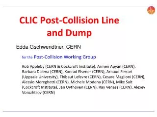
CLIC post-IP beamline. Rob Appleby CERN, University of Manchester/Cockcroft Institute ILC-CLIC LET Beam Dynamics Workshop 24/06/09. CLIC beam-beam regime Post-IP beamline layout IP backgrounds Possibility of diagnostics and focusing optics variants.

E N D
CLIC post-IP beamline Rob Appleby CERN, University of Manchester/Cockcroft Institute ILC-CLIC LET Beam Dynamics Workshop 24/06/09 • CLIC beam-beam regime • Post-IP beamline layout • IP backgrounds • Possibility of diagnostics and focusing optics variants
Design considerations for the extraction line • Beam channels: to safely transport the outgoing electron and photon beams from IP to main dump(s). • Large optical acceptance: to minimize beam loss from strong over-focusing and dispersion of low energy electrons. Requires careful optimization of energy dependent focusing and sufficient aperture. • Large geometric acceptance: to minimize beam loss from the divergent beamstrahlung photons. Requires large aperture increasing with distance. • Beam diagnostic system: to monitor luminosity, measure beam energy and polarization. Requires special downstream optics. • Collimation system: to protect magnets and post-IP diagnostic devices from unavoidable beam loss and undesirable background. • Main dump protection system: to avoid damage to dump window and prevent water boiling in the dump vessel from small undisrupted beam or under abnormal optical conditions (large errors, magnet failures). Requires enlargement of beam size at the dump window by optical means.
e+e- collision creates disrupted beam: • Huge energy spread and large x,y divergence (emittance) in the outgoing electron beam. • High power divergent beamstrahlung photon beam going in the same direction with electrons. • Plus e+e- pair production. [(in)coherent] • Issue: • Potential high beam loss in the extraction line due to over focusing of low energy electrons and divergence of the photon beam. Need collimation. Disrupted energy spread - - • Significant power in low energy tail: ~1 MW at E/E0 < 50% (out of 9.9 MW). Photons: total power ~4.1 MW long angular tails Coherent pairs: Long tails to ~ 5 mrad 170 kW in opposite charge particles
CLIC extraction concept • The baseline design uses a large crossing angle and is focusing-free, relying on the separation by dipole magnets of the disrupted beam, the beamstrahlung photons and the particles from e+e- pairs with the wrong-sign charge. • The separation bends are followed by a transport to the two dumps in dedicated transfer lines: • a short line for the wrong-sign charged particles of the coherent • pairs, to prevent the transverse beam size from increasing too much. These are dumped in an intermediate power dump • a much longer line for the disrupted beam and the beamstrahlung photons, avoiding too small spot size for the undisrupted beam at the dump window with optical growth and sweeping magnets Intermediate dump R.B. Appleby, A. Ferrari, M.D. Salt and V. Ziemann, Phys. Rev. ST Accel. Beams 12 (2009) 021001.
The separation dipoles The first magnetic elements of the CLIC post-collision line are four dipoles, spaced by 1.5m, each with a field of 0.8 T and a length of 4m (bending angle: 0.64mrad at 1.5 TeV). Collimators are interspersed to tail catch
Beam transport Beam power to dump charged particles of the coherent pairs is 205 kW. Main beam loss is 96 kW. Photons lose 100 W beam profiles allows to measure the energy spectrum of the coherent pairs All charged particles with > -0.84 and beamstrahlung photons reach the final dump. The low-energy tails are lost in either collimators or the intermediate dump, due to (mostly vertical) aperture restrictions.
Loss sources leading to IP background fluxes BDS Photon Neutron Downstream sources include Photon from 1st collimator set and intermediate dump Neutrons from intermediate and main dump This excludes direct beam-beam background e.g. pairs in solenoid field etc Muon Detector Studied in EUCARD by Appleby, Salt et al…
IP photon background from 1st mask Coherent pair loss: 1kW 29.0m 27.5m On-axis IP photon flux from 1st mask: 1.1E4 /cm2 /s To be compared to other sources and check VXD hit rate
Polarization measurement in the post-IP region? -> Need focusing variant of post-IP line to achieve similar diagnostics Slide from K. Moffeit
Focusing solution concept • The ‘baseline’ layout is a focusing-free layout, giving good beam transport • A focusing variant under development uses large aperture quadrupoles to introduce focusing - challenging due to tail over-focusing Light tail collimation Pre-dump collimation and rastoring Detector (inc. solenoid) Collimation l*ext IP beam Extraction quads Dump First extracted beam dipoles Post-IP diagnostics
Effort and Organisation Cockcroft Institute/University of Manchester: Funded under EUCARD in FP7, jointly with ASTeC (Daresbury) People: Rob Appleby, Mike Salt, EUCARD RA Topics: IP backgrounds, optics, beam transport, IR integration, and the EUCARD sub-task includes CLIC relevant aspects of ATF2 programme to study CLIC-style ultra-low betas. CERN: Edda Gschwendtner, plus a new fellow/PhD, to work on post-IP issues and coordinate the CDR writing Lau Gatignon, MDI panel chair Uppsala: Arnaud Ferrari
Summary • The non-focusing baseline post-IP layout is established, and now under study for topics such as integration and machine induced backgrounds • The design is a non-focusing layout, using staged separation dipoles and two main dumps. • The studies made with ideal colliding beams • Beam-beam maximised for vertical offsets • Extend to real start-to-end beam distributions • IP photons from first collimator system calculated with BDSIM/G4 • Extension to dumps and to neutrons being done now • Current design is non-focusing solution • Result is good beam transport to dump but harder diagnostics • First ideas for a focusing solution (minimal focusing), but magnet aperture could become an issue • A focusing lattice would allow diagnostics