Download
1 / 48
590 likes | 1.25k Views
PIN DIAGRAM OF 8085. ENGR M.ZAKIR SHAIKH Visiting Faculty,IBT LUMHS Research Associate Mehran UET,Jamshoro. Introduction to 8085. It was introduced in 1977. It is 8-bit microprocessor. Its actual name is 8085 A. It is single NMOS device. It contains 6200 transistors approx.

E N D
PIN DIAGRAM OF 8085 ENGR M.ZAKIR SHAIKH Visiting Faculty,IBT LUMHS Research Associate MehranUET,Jamshoro
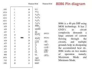
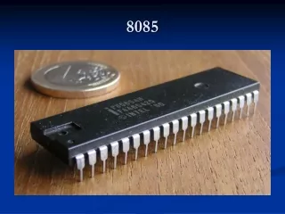
Introduction to 8085 • It was introduced in 1977. • It is 8-bit microprocessor. • Its actual name is 8085 A. • It is single NMOS device. • It contains 6200 transistors approx. • Its dimensions are 164 mm x 222 mm. • It is having 40 pins Dual-Inline-Package (DIP).
Introduction to 8085 • It has three advanced versions: • 8085 AH • 8085 AH2 • 8085 AH1 • These advanced versions are designed using HMOS technology.
Introduction to 8085 • The advanced versions consume 20% less power supply. • The clock frequencies of 8085 are: • 8085 A 3 MHz • 8085 AH 3 MHz • 8085 AH2 5 MHz • 8085 AH1 6 MHz
X1 & X2Pin 1 and Pin 2 (Input) • These are also called Crystal Input Pins. • 8085 can generate clock signals internally. • To generate clock signals internally, 8085 requires external inputs from X1 and X2.
RESET IN and RESET OUTPin 36 (Input) and Pin 3 (Output) • RESET IN: • It is used to reset the microprocessor. • It is active low signal. • When the signal on this pin is low for at least 3 clocking cycles, it forces the microprocessor to reset itself.
RESET IN and RESET OUTPin 36 (Input) and Pin 3 (Output) • Resetting the microprocessor means: • Clearing the PC and IR. • Disabling all interrupts (except TRAP). • Disabling the SOD pin. • All the buses (data, address, control) are tri-stated. • Gives HIGH output to RESET OUT pin.
RESET IN and RESET OUTPin 36 (Input) and Pin 3 (Output) • RESET OUT: • It is used to reset the peripheral devices and other ICs on the circuit. • It is an output signal. • It is an active high signal. • The output on this pin goes high whenever RESET IN is given low signal. • The output remains high as long as RESET IN is kept low.
SID and SODPin 4 (Input) and Pin 5 (Output) • SID (Serial Input Data): • It takes 1 bit input from serial port of 8085. • Stores the bit at the 8th position (MSB) of the Accumulator. • RIM (Read Interrupt Mask) instruction is used to transfer the bit.
SID and SODPin 4 (Input) and Pin 5 (Output) • SOD (Serial Output Data): • It takes 1 bit from Accumulator to serial port of 8085. • Takes the bit from the 8th position (MSB) of the Accumulator. • SIM (Set Interrupt Mask) instruction is used to transfer the bit.
Interrupt Pins • Interrupt: • It means interrupting the normal execution of the microprocessor. • When microprocessor receives interrupt signal, it discontinues whatever it was executing. • It starts executing new program indicated by the interrupt signal. • Interrupt signals are generated by external peripheral devices. • After execution of the new program, microprocessor goes back to the previous program.
Sequence of Steps Whenever There is an Interrupt • Microprocessor completes execution of current instruction of the program. • PC contents are stored in stack. • PC is loaded with address of the new program. • After executing the new program, the microprocessor returns back to the previous program. • It goes to the previous program by reading the top value of stack.
Five Hardware Interrupts in 8085 • TRAP • RST 7.5 • RST 6.5 • RST 5.5 • INTR
Classification of Interrupts • Maskable and Non-Maskable • Vectored and Non-Vectored • Edge Triggered and Level Triggered • Priority Based Interrupts
Maskable Interrupts • Maskable interrupts are those interrupts which can be enabled or disabled. • Enabling and Disabling is done by software instructions.
Maskable Interrupts • List of Maskable Interrupts: • RST 7.5 • RST 6.5 • RST 5.5 • INTR
Non-Maskable Interrupts • The interrupts which are always in enabled mode are called non-maskable interrupts. • These interrupts can never be disabled by any software instruction. • TRAP is a non-maskable interrupt.
Vectored Interrupts • The interrupts which have fixed memory location for transfer of control from normal execution. • Each vectored interrupt points to the particular location in memory.
Vectored Interrupts • List of vectored interrupts: • RST 7.5 • RST 6.5 • RST 5.5 • TRAP
Vectored Interrupts • The addresses to which program control goes: • Absolute address is calculated by multiplying the RST value with 0008 H.
Non-Vectored Interrupts • The interrupts which don't have fixed memory location for transfer of control from normal execution. • The address of the memory location is sent along with the interrupt. • INTR is a non-vectored interrupt.
Edge Triggered Interrupts • The interrupts which are triggered at leading or trailing edge are called edge triggered interrupts. • RST 7.5 is an edge triggered interrupt. • It is triggered during the leading (positive) edge.
Level Triggered Interrupts • The interrupts which are triggered at high or low level are called level triggered interrupts. • RST 6.5 • RST 5.5 • INTR • TRAP is edge and level triggered interrupt.
Priority Based Interrupts • Whenever there exists a simultaneous request at two or more pins then the pin with higher priority is selected by the microprocessor. • Priority is considered only when there are simultaneous requests.
Priority Based Interrupts • Priority of interrupts:
TRAPPin 6 (Input) • It is an non-maskable interrupt. • It has the highest priority. • It cannot be disabled. • It is both edge and level triggered. • It means TRAP signal must go from low to high. • And must remain high for a certain period of time. • TRAP is usually used for power failure and emergency shutoff.
RST 7.5Pin 7 (Input) • It is a maskable interrupt. • It has the second highest priority. • It is positive edge triggered only. • The internal flip-flop is triggered by the rising edge. • The flip-flop remains high until it is cleared by RESET IN.
RST 6.5Pin 8 (Input) • It is a maskable interrupt. • It has the third highest priority. • It is level triggered only. • The pin has to be held high for a specific period of time. • RST 6.5 can be enabled by EI instruction. • It can be disabled by DI instruction.
RST 5.5Pin 9 (Input) • It is a maskable interrupt. • It has the fourth highest priority. • It is also level triggered. • The pin has to be held high for a specific period of time. • This interrupt is very similar to RST 6.5.
INTRPin 10 (Input) • It is a maskable interrupt. • It has the lowest priority. • It is also level triggered. • It is a general purpose interrupt. • By general purpose we mean that it can be used to vector microprocessor to any specific subroutine having any address.
INTAPin 11 (Output) • It stands for interrupt acknowledge. • It is an out going signal. • It is an active low signal. • Low output on this pin indicates that microprocessor has acknowledged the INTR request.
Address and Data Pins • Address Bus: • The address bus is used to send address to memory. • It selects one of the many locations in memory. • Its size is 16-bit.
Address and Data Pins • Data Bus: • It is used to transfer data between microprocessor and memory. • Data bus is of 8-bit.
AD0 – AD7Pin 19-12 (Bidirectional) • These pins serve the dual purpose of transmitting lower order address and data byte. • During 1st clock cycle, these pins act as lower half of address. • In remaining clock cycles, these pins act as data bus. • The separation of lower order address and data is done by address latch.
A8 – A15Pin 21-28 (Unidirectional) • These pins carry the higher order of address bus. • The address is sent from microprocessor to memory. • These 8 pins are switched to high impedance state during HOLD and RESET mode.
ALEPin 30 (Output) • It is used to enable Address Latch. • It indicates whether bus functions as address bus or data bus. • If ALE = 1 then • Bus functions as address bus. • If ALE = 0 then • Bus functions as data bus.
S0 and S1Pin 29 (Output) and Pin 33 (Output) • S0 and S1 are called Status Pins. • They tell the current operation which is in progress in 8085.
IO/MPin 34 (Output) • This pin tells whether I/O or memory operation is being performed. • If IO/M = 1 then • I/O operation is being performed. • If IO/M = 0 then • Memory operation is being performed.
IO/MPin 34 (Output) • The operation being performed is indicated by S0 and S1. • If S0 = 0 and S1 = 1 then • It indicates WRITE operation. • If IO/M = 0 then • It indicates Memory operation. • Combining these two we get Memory Write Operation.
RDPin 32 (Output) • RD stands for Read. • It is an active low signal. • It is a control signal used for Read operation either from memory or from Input device. • A low signal indicates that data on the data bus must be placed either from selected memory location or from input device.
WRPin 31 (Output) • WR stands for Write. • It is also active low signal. • It is a control signal used for Write operation either into memory or into output device. • A low signal indicates that data on the data bus must be written into selected memory location or into output device.
READYPin 35 (Input) • This pin is used to synchronize slower peripheral devices with fast microprocessor. • A low value causes the microprocessor to enter into wait state. • The microprocessor remains in wait state until the input at this pin goes high.
HOLDPin 38 (Input) • HOLD pin is used to request the microprocessor for DMA transfer. • A high signal on this pin is a request to microprocessor to relinquish the hold on buses. • This request is sent by DMA controller. • Intel 8257 and Intel 8237 are two DMA controllers.
HLDAPin 39 (Output) • HLDA stands for Hold Acknowledge. • The microprocessor uses this pin to acknowledge the receipt of HOLD signal. • When HLDA signal goes high, address bus, data bus, RD, WR, IO/M pins are tri-stated. • This means they are cut-off from external environment.
HLDAPin 39 (Output) • The control of these buses goes to DMA Controller. • Control remains at DMA Controller until HOLD is held high. • When HOLD goes low, HLDA also goes low and the microprocessor takes control of the buses.
VSS and VCCPin 20 (Input) and Pin 40 (Input) • +5V power supply is connected to VCC. • Ground signal is connected to VSS.