Download
1 / 3
40 likes | 156 Views
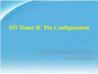
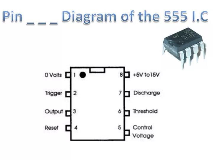
Pin _ _ _ Diagram of the 555 I.C. The. MicroChip. On. Off. Microchips are small electronic circuits that have many different components built onto a small piece of silicon (which is a semi-conductor) housed in a plastic case. These can be referred to as IC’s (integrated circuits).

E N D
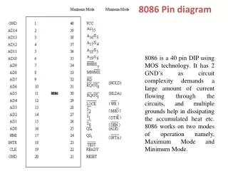
The MicroChip On Off Microchips are small electronic circuits that have many different components built onto a small piece of silicon (which is a semi-conductor) housed in a plastic case. These can be referred to as IC’s (integrated circuits). All IC’s are usually set up in a DIL (Dual In Line) configuration, this is where there are two sets of parallel connections (the pins). As you can be seen from the diagram to the left the I.C has a small circle, this normally identifies pin 1, and the remaining pins are numbered anticlockwise (as shown in the diagram). The 555 Timer IC • These are cheap and come in an 8-pin DIL pack. • The main advantage of using this IC is that it can be used as both an astable and monostable timer. It is possible to use discrete components such as resistors, capacitors, etc to achieve the same results as a 555 timer IC however it is more usual to use the 555 timer IC. • Monostable: • This IC has only one stable state – this means that it remains off (logic 0) until triggered • When a positive voltage is applied to the trigger, the output goes high (logic 1) for a time determined by the values of the resistor and capacitor – it then returns to its original state until triggered again. • Possible use for this would be a burglar alarm, which once activated sounds for a set time.
555 IC timer I.S :- Check your understanding Look at the pin out diagram, between which two pins would you connect a power supply? ____&___ To which pin would you connect a switch to? ____________ On what pin have you connected your buzzer? __________ • What are the Two Main reasons why we would use an I.C rather than using discrete components such as resistors, capacitors and transistors to create the same effects? • ________________________________________________________________________________________________________________________________________________________________________________________ • ________________________________________________________________________________________________________________________________________________________________________________________ Draw a diagram to explain what happens when the 555 timer IC is triggered (pin 2 is activated). You will need to label and explain your diagram. ____________________________________________________________________________________________________________________________________________________________________________________________________________________