Download
1 / 36
1.47k likes | 2.97k Views
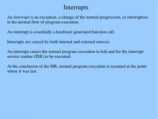
8085 Interrupts. Interrupts. Interrupt is a process where an external device can get the attention of the microprocessor. The process starts from the I/O device The process is asynchronous . TYPES OF INTERRUPT: SOFTWARE AND HARDWARE

E N D
8085 Interrupts LAKSHMI.B.E.
Interrupts • Interrupt is a process where an external device can get the attention of the microprocessor. • The process starts from the I/O device • The process is asynchronous. TYPES OF INTERRUPT: SOFTWARE AND HARDWARE VECTORED AND MASKABLE AND NON VECTORED NON MASKABLE LAKSHMI.B.E.
Classification of Interrupts • Interrupts can be classified into two types: • Maskable Interrupts(Can be delayed or Rejected) • Enable Or Disable By EI And DI Instruction • Non-Maskable Interrupts (Can not be delayed or Rejected) • Interrupts can also be classified into: • Vectored (the address of the service routine is hard-wired) • Non-vectored (the address of the service routine needs to be supplied externally by the device) LAKSHMI.B.E.
Interrupts • An interrupt is considered to be an emergency signal that may be serviced. • The Microprocessor may respond to it as soon as possible. • What happens when MP is interrupted ? • When the Microprocessor receives an interrupt signal, it suspends the currently executing program and jumps to an Interrupt Service Routine (ISR) to respond to the incoming interrupt. • Each interrupt will most probably have its own ISR. LAKSHMI.B.E.
Responding to Interrupts • Responding to an interrupt may be immediate or delayed depending on whether the interrupt is maskable or non-maskable and whether interrupts are being masked or not. • There are two ways of redirecting the execution to the ISR depending on whether the interrupt is vectored or non-vectored. • Vectored: The address of the subroutine is already known to the Microprocessor • Non Vectored: The device will have to supply the address of the subroutine to the Microprocessor LAKSHMI.B.E.
The 8085 Interrupts • When a device interrupts, it actually wants the MP to give a service which is equivalent to asking the MP to call a subroutine. This subroutine is called ISR (Interrupt Service Routine) • The ‘EI’ instruction is a one byte instruction and is used to Enable the non-maskable interrupts. • The ‘DI’ instruction is a one byte instruction and is used to Disable the non-maskable interrupts. • The 8085 has a single Non-Maskable interrupt. • The non-maskable interrupt is notaffected by the value of the Interrupt Enable flip flop. LAKSHMI.B.E.
The 8085 Interrupts • The 8085 has 5 interrupt inputs. • The INTR input. • The INTR input is the only non-vectored interrupt. • INTR is maskable using the EI/DI instruction pair. • RST 5.5, RST 6.5, RST 7.5 are all automatically vectored. • RST 5.5, RST 6.5, and RST 7.5 are all maskable. • TRAP is the only non-maskable interrupt in the 8085 • TRAP is also automatically vectored LAKSHMI.B.E.
8085 Interrupts LAKSHMI.B.E.
Interrupt Vectors and the Vector Table • An interrupt vector is a pointer to where the ISR is stored in memory. • All interrupts (vectored or otherwise) are mapped onto a memory area called the Interrupt Vector Table (IVT). • The IVT is usually located in memory page 00 (0000H - 00FFH). • The purpose of the IVT is to hold the vectors that redirect the microprocessor to the right place when an interrupt arrives. LAKSHMI.B.E.
The 8085 Non-Vectored Interrupt Process • The interrupt process should be enabled using the EI instruction. • The 8085 checks for an interrupt during the execution of every instruction. • If INTR is high, MP completes current instruction, disables the interrupt and sends INTA (Interrupt acknowledge) signal to the device that interrupted • INTA allows the I/O device to send a RST instruction through data bus. • Upon receiving the INTA signal, MP saves the memory location of the next instruction on the stack and the program is transferred to ‘call’ location (ISR Call) specified by the RST instruction LAKSHMI.B.E.
The 8085 Non-Vectored Interrupt Process • Microprocessor Performs the ISR. • ISR must include the ‘EI’ instruction to enable the further interrupt within the program. • RET instruction at the end of the ISR allows the MP to retrieve the return address from the stack and the program is transferred back to where the program was interrupted. LAKSHMI.B.E.
The 8085 Maskable/Vectored Interrupts • The 8085 has 3 Masked/Vectored interrupt inputs. • RST 5.5, RST 6.5, RST 7.5 • They are all maskable. • They are automatically vectored according to the following table: • The vectors for these interrupt fall in between the vectors for the RST instructions. That’s why they have names like RST 5.5 (RST 5 and a half). LAKSHMI.B.E.
Masking RST 5.5, RST 6.5 and RST 7.5 • These three interrupts are masked at two levels: • Through the Interrupt Enable flip flop and the EI/DI instructions. • The Interrupt Enable flip flop controls the whole maskable interrupt process. • Through individual mask flip flops that control the availability of the individual interrupts. • These flip flops control the interrupts individually. LAKSHMI.B.E.
Maskable Interrupts and vector locations RST7.5 Memory RST 7.5 M 7.5 RST 6.5 M 6.5 RST 5.5 M 5.5 INTR ** See Fig 12.5 of the Text Book for a detailed look Interrupt Enable Flip Flop LAKSHMI.B.E.
The 8085 Maskable/Vectored Interrupt Process • The interrupt process should be enabled using the EI instruction. • The 8085 checks for an interrupt during the execution of every instruction. • If there is an interrupt, and if the interrupt is enabled using the interrupt mask, the microprocessor will complete the executing instruction, and reset the interrupt flip flop. • The microprocessor then executes a call instruction that sends the execution to the appropriate location in the interrupt vector table. LAKSHMI.B.E.
The 8085 Maskable/Vectored Interrupt Process • When the microprocessor executes the call instruction, it saves the address of the next instruction on the stack. • The microprocessor jumps to the specific service routine. • The service routine must include the instruction EI to re-enable the interrupt process. • At the end of the service routine, the RET instruction returns the execution to where the program was interrupted. LAKSHMI.B.E.
Manipulating the Masks • The Interrupt Enable flip flop is manipulated using the EI/DI instructions. • The individual masks for RST 5.5, RST 6.5 and RST 7.5 are manipulated using the SIM instruction. • This instruction takes the bit pattern in the Accumulator and applies it to the interrupt mask enabling and disabling the specific interrupts. LAKSHMI.B.E.
7 6 5 4 3 2 1 0 SDO M5.5 M7.5 MSE R7.5 M6.5 SDE XXX How SIM Interprets the Accumulator RST5.5 Mask Serial Data Out } RST6.5 Mask 0 - Available 1 - Masked RST7.5 Mask Mask Set Enable 0 - Ignore bits 0-2 1 - Set the masks according to bits 0-2 Enable Serial Data 0 - Ignore bit 7 1 - Send bit 7 to SOD pin Not Used Force RST7.5 Flip Flop to reset LAKSHMI.B.E.
SIM and the Interrupt Mask • Bit 0 is the mask for RST 5.5 • Bit 1 is the mask for RST 6.5 • Bit 2 is the mask for RST 7.5. • If the mask bit is 0, the interrupt is available. • If the mask bit is 1, the interrupt is masked. LAKSHMI.B.E.
Bit 3 (Mask Set Enable - MSE) is an enable for setting the mask. • If it is set to 0 the mask is ignored and the old settings remain. • If it is set to 1, the new setting are applied. • The SIM instruction is used for multiple purposes and not only for setting interrupt masks. • It is also used to control functionality such as Serial Data Transmission. • Therefore, bit 3 is necessary to tell the microprocessor whether or not the interrupt masks should be modified LAKSHMI.B.E.
SIM and the Interrupt Mask • The RST 7.5 interrupt is the only 8085 interrupt that has memory. • If a signal on RST7.5 arrives while it is masked, a flip flop will remember the signal. • When RST7.5 is unmasked, the microprocessor will be interrupted even if the device has removed the interrupt signal. • This flip flop will be automatically reset when the microprocessor responds to an RST 7.5 interrupt. • Bit 4 of the accumulator in the SIM instruction allows explicitlyresetting the RST 7.5 memory even if the microprocessor did not respond to it. • Bit 5 is not used by the SIM instruction LAKSHMI.B.E.
Using the SIM Instruction to Modify the Interrupt Masks • Example: Set the interrupt masks so that RST5.5 is enabled, RST6.5 is masked, and RST7.5 is enabled. • First, determine the contents of the accumulator - Enable 5.5 bit 0 = 0 - Disable 6.5 bit 1 = 1 - Enable 7.5 bit 2 = 0 - Allow setting the masks bit 3 = 1 - Don’t reset the flip flop bit 4 = 0 - Bit 5 is not used bit 5 = 0 - Don’t use serial data bit 6 = 0 - Serial data is ignored bit 7 = 0 M7.5 M6.5 M5.5 SDO MSE R7.5 SDE XXX 1 0 0 0 0 0 1 0 Contents of accumulator are: 0AH EI ; Enable interrupts including INTR MVI A, 0A ; Prepare the mask to enable RST 7.5, and 5.5, disable 6.5 SIM ; Apply the settings RST masks LAKSHMI.B.E.
Triggering Levels • RST 7.5 is positive edge sensitive. • When a positive edge appears on the RST7.5 line, a logic 1 is stored in the flip-flop as a “pending” interrupt. • Since the value has been stored in the flip flop, the line does not have to be high when the microprocessor checks for the interrupt to be recognized. • The line must go to zero and back to one before a new interrupt is recognized. • RST 6.5 and RST 5.5 are level sensitive. • The interrupting signal must remain present until the microprocessor checks for interrupts. LAKSHMI.B.E.
Determining the Current Mask Settings • RIM instruction: Read Interrupt Mask • Load the accumulator with an 8-bit pattern showing the status of each interrupt pin and mask. LAKSHMI.B.E.
RIM sets the Accumulator’s different bits LAKSHMI.B.E.
The RIM Instruction and the Masks • Bits 0-2 show the current setting of the mask for each of RST 7.5, RST 6.5 and RST 5.5 • They return the contents of the three mask flip flops. • They can be used by a program to read the mask settings in order to modify only the right mask. • Bit 3 shows whether the maskable interrupt process is enabled or not. • It returns the contents of the Interrupt Enable Flip Flop. • It can be used by a program to determine whether or not interrupts are enabled. LAKSHMI.B.E.
The RIM Instruction and the Masks • Bits 4-6 show whether or not there are pending interrupts on RST 7.5, RST 6.5, and RST 5.5 • Bits 4 and 5 return the current value of the RST5.5 and RST6.5 pins. • Bit 6 returns the current value of the RST7.5 memory flip flop. • Bit 7 is used for Serial Data Input. • The RIM instruction reads the value of the SID pin on the microprocessor and returns it in this bit. LAKSHMI.B.E.
Pending Interrupts • Since the 8085 has five interrupt lines, interrupts may occur during an ISR and remain pending. • Using the RIM instruction, it is possible to can read the status of the interrupt lines and find if there are any pending interrupts. • See the example of the class LAKSHMI.B.E.
TRAP • TRAP is the only non-maskable interrupt. • It does not need to be enabled because it cannot be disabled. • It has the highest priority amongst interrupts. • It is edge and level sensitive. • It needs to be high and stay high to be recognized. • Once it is recognized, it won’t be recognized again until it goes low, then high again. • TRAP is usually used for power failure and emergency shutoff. LAKSHMI.B.E.
Issues in Implementing INTR Interrupts • How long must INTR remain high? • The microprocessor checks the INTR line one clock cycle before the last T-state of each instruction. • The INTR must remain active long enough to allow for the longest instruction. • The longest instruction for the 8085 is the conditional CALL instruction which requires 18 T-states. • Therefore, the INTR must remain active for 17.5 T-states. • If f= 3MHZ then T=1/f and so, INTR must remain active for [ (1/3MHZ) * 17.5 ≈ 5.8 micro seconds]. LAKSHMI.B.E.
Issues in Implementing INTR Interrupts • How long can the INTR remain high? • The INTR line must be deactivated before the EI is executed. Otherwise, the microprocessor will be interrupted again. • Once the microprocessor starts to respond to an INTR interrupt, INTA becomes active (=0). Therefore,INTR should be turned off as soon as the INTA signal is received. LAKSHMI.B.E.
PIN 7 RST 7.5 M7.5’ R 7.5 RST 7.5 ACKNOWLEDGEMENT MSE
The End … Thank you …