Download
1 / 39
390 likes | 440 Views
chapter 59. Disc Brakes. FIGURE 59.1 Minimum thickness for various types of disc brake pads. Pad wear sensors often make a “chirping” sound when the vehicle is moving if the pads are worn. Do not confuse that noise for a defective wheel bearing or other fault.

E N D
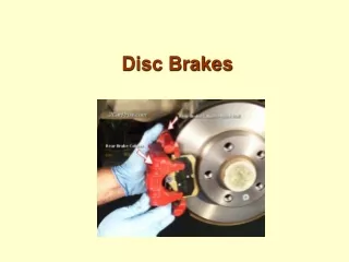
chapter59 Disc Brakes
FIGURE 59.1 Minimum thickness for various types of disc brake pads. Pad wear sensors often make a “chirping” sound when the vehicle is moving if the pads are worn. Do not confuse that noise for a defective wheel bearing or other fault.
FIGURE 59.2 This cracked disc brake pad must be replaced even though it is thicker than the minimum allowed by the vehicle manufacturer.
FIGURE 59.3 Be careful to observe the direction in which replacement linings are facing. Some vehicle manufacturers offset the friction material on the steel backing to help prevent or minimize tapered pad wear.
FIGURE 59.4 Most disc brake calipers have a brake inspection opening. For a thorough inspection, however, the caliper should be removed and the entire braking system thoroughly inspected.
FIGURE 59.5 Both rear- and forward-mounted calipers have the bleeder valve at the top. Some calipers will fit on the wrong side of the vehicle, yet not be able to be bled correctly because the bleeder valve would point down, allowing trapped air to remain inside the caliper bore. If both calipers are being removed at the same time, mark them “left” and “right.”
FIGURE 59.6 Many manufacturers recommend removing one-half of the brake fluid from the master cylinder before servicing disc brakes. Use a squeeze bulb and dispose of the used brake fluid properly.
FIGURE 59.7 Most manufacturers recommend that the bleeder valve be opened and the brake fluid forced into a container rather than back into the master cylinder reservoir. This helps prevent contaminated brake fluid from being forced into the master cylinder where the dirt and contamination could cause problems.
FIGURE 59.8 Many calipers use a hollow “banjo bolt” to retain the flexible brake line to the caliper housing. The fitting is usually round like a banjo. The copper washers should always be replaced and not reused.
FIGURE 59.9 Caliper retaining bolts are often called guide pins. These guide pins are used to retain the caliper to the steering knuckle. These pins also slide through metal bushings and rubber O-rings.
FIGURE 59.10 If the caliper is not being removed, it must be supported properly so that the weight of the caliper is not pulling on the flexible rubber brake line. A suitable piece of wire, such as a coat hanger, may be used.
FIGURE 59.11 These pads were found to be cracked and a section was missing from a part of one pad.
FIGURE 59.12 A loaded caliper includes all hardware and shims with the correct pads all in one convenient package, ready to install on the vehicle.
FIGURE 59.13 Floating calipers must be able to slide during normal operation. Therefore, there must be clearance between the caliper and the caliper mounting pads (abutments). Too little clearance will prevent the caliper from sliding and too much clearance will cause the caliper to make a clunking noise when the brakes are applied.
FIGURE 59.14 Using an air-powered sanding disc to clean the caliper mount pads.
FIGURE 59.15 Determine which face of the special tool best fits the holes or slots in the piston. Sometimes needle-nose pliers can be used to rotate the piston back into the caliper bore.
FIGURE 59.16 Note the twisted flexible brake line. This was caught by an automotive instructor before the brake work on the vehicle was completed. The twisted brake line can cause brake hose failure if not corrected.
FIGURE 59.17 For best braking performance, purchase replacement disc brake pads that include all clips and shims specified by the vehicle manufacturer. Some pads even come with a package of the specified grease to use on the shims to reduce the possibility of brake noise.
FIGURE 59.18 Notice the beveled pads. The shape of the pad helps reduce brake noise.
FIGURE 59.19 The screwdriver blade is used to keep the piston applied to allow self-adjustment to occur when the brake pedal is released.
UNFIGURE 59.1 After properly setting the hoist pads under the vehicle, raise the vehicle to chest level and remove the lug nuts.
UNFIGURE 59.2 Remove the wheel/tire assembly and place it where it will not get in the way or be damaged.
UNFIGURE 59.3 It is recommended that the entire brake assembly be washed using a commercially available cleaner to avoid the possibility of allowing brake dust from becoming airborne.
UNFIGURE 59.4 If a commercial brake cleaning unit is not available, use brake cleaner from an aerosol or pressurized container.
UNFIGURE 59.5 To service the front disc brake pads on this vehicle, loosen the upper caliper retainer bolt and remove the lower bolt.
UNFIGURE 59.6 After the lower caliper bolt has been removed, the caliper assembly can be lifted upward by pivoting on the upper retaining bolt.
UNFIGURE 59.7 Use mechanic’s wire to hold the caliper in the raised position to allow access to the disc brake pads.
UNFIGURE 59.8 Notice that both the inboard and outboard pad remain attached to the steering knuckle. The pads and shims can be lifted off.
UNFIGURE 59.9 A C-clamp can be used to push the piston into the caliper, but be sure to open the bleeder valve first.
UNFIGURE 59.10 The bleeder valve should be opened to allow the old brake fluid to flow out of the caliper and not be forced up into the ABS hydraulic unit or master cylinder.
UNFIGURE 59.11 Often factory replacement disc brake pads include noise-dampening shims, antirattle clips, and special “moly” disc brake grease that is to be used on the shims.
UNFIGURE 59.12 All hardware, including this anchor shim, should be replaced.
UNFIGURE 59.13 Install new shims after thoroughly cleaning the steering knuckle area of any rust using a wire brush or other suitable tool.
UNFIGURE 59.14 The replacement disc brake pads are installed next to the rotor and held in place by the tension of the anchor shims.
UNFIGURE 59.15 After double-checking that all shims, clips, and spacers are correctly installed, lower the calipers and install this lower attaching bolt.
UNFIGURE 59.16 Torque the retaining bolts to factory specifications. Repeat the process on the other side and bleed the hydraulic system.
UNFIGURE 59.18 Torque the lug nuts to factory specifications or use a torque-limiting adapter. Test drive the vehicle before returning it to the customer.