Download
1 / 72
770 likes | 988 Views
CHAPTER 12 Disc Brakes. http://www.youtube.com/watch?v=F4fAPpj3p48&feature=related intro 3d Animation. OBJECTIVES. After studying Chapter 12, the reader will be able to: Prepare for the Brakes (A5) ASE certification test content area “C” (Disc Brake Diagnosis and Repair).

E N D
CHAPTER 12 Disc Brakes
http://www.youtube.com/watch?v=F4fAPpj3p48&feature=related intro 3d Animation
OBJECTIVES After studying Chapter 12, the reader will be able to: • Prepare for the Brakes (A5) ASE certification test content area “C” (Disc Brake Diagnosis and Repair). • Describe how disc brakes function. • Name the parts of a typical disc brake system. • Describe the construction of disc brake pads. • Describe the difference between fixed caliper and floating or sliding caliper. • Explain the difference between a standard caliper and a low-drag caliper.
Anchor plate Antirattle clips Aramid fiber Bonded linings Brake block Brake pad CFRC Fixed brake caliper Floating caliper Gas fade Integrally molded Kevlar Lining fade Low-drag caliper Mechanical fade Mold bonded lining NAO NAS Natural frequency Nonasbestos Pad wear indicators Pin-slider caliper Riveted linings Semimets Sintered metal Sintering Sliding caliper Swept area Water fade Ways KEY TERMS
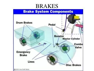
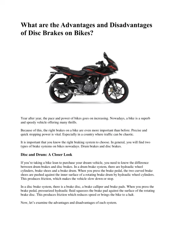
DISC BRAKESPARTS AND OPERATION • Disc brakes use a piston(s) to squeeze friction material (pads) on both sides of a rotating disc (rotor). • Disc may be spelled disk by some manufacturers, but disc is the SAE (Society of Automotive Engineers) term and the most commonly used spelling in the industry. • The rotor is attached to and stops the wheel.
DISC BRAKESPARTS AND OPERATION • Disc brakes are used on the front wheels of late-model vehicles, and on the rear wheels of an increasing number of automobiles. • Disc brakes were adopted primarily because they can supply greater stopping power than drum brakes with less likelihood of fade. • This makes disc brakes especially well suited for use as front brakes, which must provide 60% to 80% of the vehicle’s total stopping power.
DISC BRAKESDISC BRAKE ADVANTAGES • The main advantages of the disc brake include the following. • FADE RESISTANCE • SELF-ADJUSTING ABILITY • FREEDOM FROM PULL • Disc brakes are resistant to all kinds of fade, including the following: • Mechanical fade • Lining fade • Gas fade • Water fade
FIGURE 12–1 A typical disc brake assembly. DISC BRAKESDISC BRAKE ADVANTAGES
FIGURE 12–2 Braking force is applied equally to both sides of the brake rotor. DISC BRAKESDISC BRAKE ADVANTAGES
FIGURE 12–3 Disc brakes can absorb and dissipate a great deal of heat. During this demonstration, the brakes were gently applied as the engine drove the front wheels until the rotor became cherry red. During normal braking, the rotor temperature can exceed 350°F (180°C), and about 1,500°F (800°C) on a race vehicle. DISC BRAKESDISC BRAKE ADVANTAGES
Over Heated rotors • http://www.youtube.com/watch?v=xmW9c-7KCqA • http://www.youtube.com/watch?NR=1&feature=endscreen&v=6-wP2cwJu7I fire disk brakes
FIGURE 12–4 Slots and holes in the brake linings help prevent gas and water fade. DISC BRAKESDISC BRAKE ADVANTAGES
FIGURE 12–5 The square-cut O-ring not only seals hydraulic brake fluid, but also retracts the caliper piston when the brake pedal is released. DISC BRAKESDISC BRAKE ADVANTAGES
DISC BRAKESDISC BRAKE DISADVANTAGES • The most notable fact about the disadvantages of disc brakes is that there are so few. • The weaknesses of disc brakes include the following. • No Self-Energizing or Servo Action • Brake Noise • Brake Dust • Poor Parking Brake Performance
Check the Tire Size for a Pulling Problem • If an unequal braking problem is being diagnosed, check that the front tires match and that the rear tires match. Brakes slow and stop wheels. Unequal diameter tires create an unequal braking force. The result may be a pulling toward one side while braking. Tire diameter can vary from one tire manufacturer to another even though the size designation is the same. Even slight differences in the wear of tires can cause a different tire diameter and, therefore, a different braking force.
FIGURE 12–6 Antirattle clips reduce brake pad movement and vibration. DISC BRAKESDISC BRAKE DISADVANTAGES
FIGURE 12–7 Antivibration shims are used behind the pads on many disc brake caliper designs. DISC BRAKESDISC BRAKE DISADVANTAGES
Wax the Wheels • Brake dust from semimetallic brake pads often discolors the front wheels. Customers often complain to service technicians about this problem, but it is normal for the front wheels to become dirty because the iron and other metallic and nonmetallic components wear off the front disc brake pads and adhere to the wheel covers. A coat of wax on the wheels or wheel covers helps prevent damage and makes it easier to wash off the brake dust.
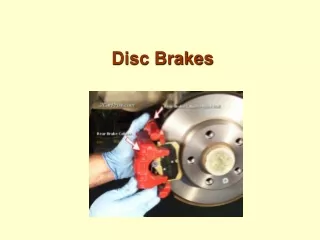
DISC BRAKE CONSTRUCTION • A disc brake is relatively simple compared with a drum brake. • The major disc brake friction assembly components include the following. • CALIPER • SPLASH SHIELD
FIGURE 12–8 This brake caliper attaches to the front spindle. DISC BRAKE CONSTRUCTION
FIGURE 12–9 A rear disc brake caliper often attaches to a mounting bracket on the rear axle housing. DISC BRAKE CONSTRUCTION
FIGURE 12–10 A typical disc brake pad. DISC BRAKE PADS • The lining of a disc brake is part of an assembly called the brake pad.
FIGURE 12–11 To prevent noise, bent tabs on the backing plate hold some brake pads to the caliper housing. DISC BRAKE PADS
FIGURE 12–12 Holes in the backing plate are a common method of locating a pad in the caliper. DISC BRAKE PADS
FIGURE 12–13 Retainer springs lock the pad to the caliper piston to prevent brake noise. DISC BRAKE PADS
FIGURE 12–14 The lining edges of some brake pads are tapered to help prevent vibration. DISC BRAKE PADS
DISC BRAKE PADSPAD WEAR INDICATORS • Although not required by law, a growing number of vehicle manufacturers are fitting pad wear indicators to their brakes for safety reasons. • Pad wear indicators are either mechanical or electrical, and signal the driver when the lining material has worn to the point where pad replacement is necessary. • A mechanical wear indicator is a small spring-steel tab riveted to the pad backing plate. • When the friction material wears to a predetermined thickness, the tab contacts the rotor and makes a squealing or chirping noise (when the brakes are not applied) that alerts the driver to the need for service.
FIGURE 12–15 Typical pad wear sensor operation. It is very important that the disc brake pads are installed on the correct side of the vehicle to be assured that the wear sensor will make a noise when the pads are worn. If the pads with a sensor are installed on the opposite side of the vehicle, the sensor tab is turned so that the rotor touches it going the opposite direction. Usually the correct direction is where the rotor contacts the sensor before contacting the pads when the wheels are being rotated in the forward direction. DISC BRAKE PADSPAD WEAR INDICATORS
FIGURE 12–16 Electrical wear indicators ground a warning light circuit when the pads need replacement. DISC BRAKE PADSPAD WEAR INDICATORS
DISC BRAKE PADSPAD ASSEMBLY METHODS • As mentioned previously, there are several methods that are used to mount brake linings, including: • Riveted linings • Bonded linings • Mold-bonded linings
FIGURE 12–17 Mold-bonded linings are commonly used in many applications. DISC BRAKE PADSPAD ASSEMBLY METHODS
DISC BRAKE PADSBRAKE LINING COMPOSITION • The various ingredients in brake lining are mixed and molded into the shape of the finished product. • The fibers in the material are the only thing holding this mixture together. • A large press is used to force the ingredients together to form a brake block, which eventually becomes the brake lining.
Competitively Priced Brakes • The term competitively priced means lower cost. Most brake manufacturers offer “premium” as well as lower-price linings, to remain competitive with other manufacturers or with importers of brake lining material produced overseas by U.S. or foreign companies. Organic asbestos brake lining is inexpensive to manufacture. In fact, according to warehouse distributors and importers, the box often costs more than the brake lining inside. • Professional brake service technicians should only install brake linings and pads that will give braking performance equal to that of the original factory brakes. For best results, always purchase high-quality brake parts from a known brand-name manufacturer.
DISC BRAKE PADSBRAKE LINING COMPOSITION • SEMIMETALLIC FRICTION MATERIAL • NONASBESTOS FRICTION MATERIAL • CARBON FIBER FRICTION MATERIAL • CERAMIC FRICTION MATERIAL
What Does “D3EA” Mean? • Original equipment brake pads and shoes are required to comply with the Federal Motor Vehicle Safety Standard (FMVSS) 135, which specifies maximum stopping distances. There is also a requirement for fade resistance, but no standard for noise or wear. Aftermarket (replacement) brake pads and shoes are not required to meet the FMVSS standard. However, several manufacturers of replacement brake pads and shoes are using a standardized test that closely matches the FMVSS standard and is called the “Dual Dynamometer Differential Effectiveness Analysis” or D3EA. This test is currently voluntary and linings that pass the test can have a “D3EA certified” seal placed on the product package.
DISC BRAKE PADSEDGE CODES • As explained previously, the lining edge codes help identify the coefficient of friction. • These codes were established by the SAE (Society of Automotive Engineers) and published as Standard J886a.
BRAKE ROTORS • The brake rotor provides the friction surfaces for the brake pads to rub against. • The rotor, the largest and heaviest part of a disc brake, is usually made of cast iron because that metal has excellent friction and wear properties. • There are two basic types of rotors: • Solid—Solid rotors are most often used on the rear of vehicles equipped with four-wheel disc brakes. • Vented—Vented rotors have radial cooling passages cast between the friction surfaces.
FIGURE 12–18 Disc brake rotors can be either solid or vented. BRAKE ROTORS
DISC BRAKE DESIGNS • There are basically three types of calipers: fixed, floating, and sliding designs. • FIXED CALIPER DESIGN • FIXED CALIPER ADVANTAGES • FIXED CALIPER DISADVANTAGES • FLOATING AND SLIDING CALIPER DESIGN • NORMAL CALIPER OPERATION • WEAR COMPENSATION • FLOATING AND SLIDING CALIPER ADVANTAGES • FLOATING AND SLIDING CALIPER DISADVANTAGES
FIGURE 12–19 (a) Many fixed caliper disc brakes use a simple retaining pin to hold the disc brake pads. (b) Removing the retainer pads allows the brake pads to be removed. (c) Notice the cross-over hydraulic passage that connects both sides of the caliper. DISC BRAKE DESIGNS
FIGURE 12–20 This floating caliper mounts on a separate anchor plate that bolts to the vehicle suspension. DISC BRAKE DESIGNS
FIGURE 12–21 Hydraulic force on the piston (left) is applied to the inboard pad and the caliper housing itself. The reaction of the piston pushing against the rotor causes the entire caliper to move toward the inside of the vehicle (large arrow). Since the outboard pad is retained by the caliper, the reaction of the moving caliper applies the force of the outboard pad against the outboard surface of the rotor. DISC BRAKE DESIGNS
FIGURE 12–22 Caliper flex can cause tapered wear of the brake lining. DISC BRAKE DESIGNS
Brake pad conditions • http://www.monroebrakes.com/support/common-brake-conditions
FIGURE 12–23 A typical single-piston floating caliper. In this type of design, the entire caliper moves when the single piston is pushed out of the caliper during a brake application. When the caliper moves, the outboard pad is pushed against the rotor. DISC BRAKE DESIGNSFLOATING CALIPER OPERATION • The body of a floating caliper does not make direct metal-to-metal contact with the anchor plate.
FIGURE 12–24 Floating calipers are supported by rubber O-rings or plastic bushings. DISC BRAKE DESIGNSFLOATING CALIPER OPERATION
FIGURE 12–25 Metal guide pins and sleeves are used to retain and locate floating calipers. DISC BRAKE DESIGNSFLOATING CALIPER OPERATION
What Is a Low-Drag Caliper? • A low-drag caliper differs from a standard caliper in the area of the square-cut O-ring. A V-shaped cutout allows the O-ring to deflect more and, as a result, is able to pull the caliper piston back into the bore when the brakes are released. Because of this further movement, the brake pads are pulled further from the rotor and are less likely to drag. The negative aspect of this design is that greater volume of brake fluid is needed to achieve a brake application. To compensate for this need for greater brake fluid volume, a quick-take-up master cylinder was designed and is used whenever low-drag calipers are used.