Download
1 / 16
210 likes | 533 Views
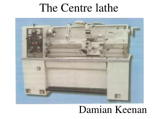
Lathe Practice. Introduction. Lathe is a machine, which removes the metal from a piece of work to the required shape &size. Types of Lathe. Engine Lathe The most common form of lathe, motor driven and comes in large variety of sizes and shapes. Bench Lathe

E N D
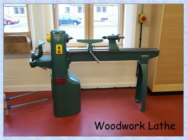
Introduction Lathe is a machine, which removes the metal from a piece of work to the required shape &size
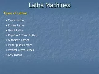
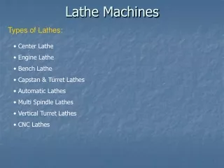
Types of Lathe • Engine Lathe • The most common form of lathe, motor driven and comes in large variety of sizes and shapes. • Bench Lathe • A bench top model usually of low power used to make precision machine small work pieces. • Tracer Lathe • a lathe that has the ability to follow a template to copy a shape or contour.
Automatic Lathe • A lathe in which the work piece is automatically fed and removed without use of an operator. Cutting operations are automatically controlled by a • sequencer of some form • Turret Lathe • lathe which have multiple tools mounted on turret either attached to the tailstock or the cross-slide, which allows for quick changes in tooling and cutting operations. • Computer Controlled Lathe • A highly automated lathe, where both cutting, loading, tool changing, and part unloading are automatically controlled by computer coding.
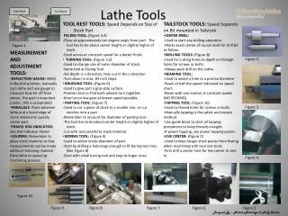
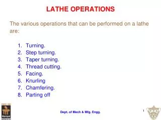
Lathe Operations Turning:produce straight, conical, curved, or grooved workpieces Facing: to produce a flat surface at the end of the part or for making face grooves. Boring: to enlarge a hole or cylindrical cavity made by a previous process or to produce circular internal grooves. Drilling: to produce a hole by fixing a drill in the tailstock Threading: to produce external or internal threads Knurling: to produce a regularly shaped roughness on cylindrical surfaces
Cutting Tools Single point cutting tool
Work Holding Devices Fig : (a) and (b) Schematic illustrations of a draw-in-type collets. The workpiece is placed in the collet hole, and the conical surfaces of the collet are forced inward by pulling it with a draw bar into the sleeve. (c) A push-out type collet. (d) Workholding of a part on a face plate.
Three jaw chuck - For holding cylindrical stock centered. - For facing/center drilling the end of your aluminum stock Four-Jaw Chuck - This is independent chuck generally has four jaws , which are adjusted individually on the chuck face by means of adjusting screws
Collet Chuck Collet chuck is used to hold small workpieces • Thin jobs can be held by means of magnetic chucks. Magnetic Chuck Thin jobs can be held by means of magnetic chucks.
Simple Problems Problem -1 A mild steel rod having 50 mm diameter and 500 mm length is to be turned on a lathe. Determine the machining time to reduce the rod to 45 mm in one pass when cutting speed is 30 m/min and a feed of 0.7 mm/rev is used.
Solution Given data: D = 50 mm, Lj= 500 mm v = 30 m/min, f = 0.7 mm/rev Substituting the values of v and D in V = ΠDN/1000 M/min Required spindle speed as: N = 191 rpm
Simple Problems • Problem -2 Determine the angle at which the compound rest would be swiveled for cutting a taper on a work piece having a length of 150 mm and outside diameter 80 mm. The smallest diameter on the tapered end of the rod should be 50 mm and the required length of the tapered portion is 80 mm. Solution • Given data: D1 = 80 mm, D2 = 50 mm, Lj = 80 mm (with usual notations) • tan = (80-50) / 280 or = 10.620 • The compound rest should be swiveled at 10.62o
References • Book • work shop Technolgy by Hajra choudry • Advances in Manufacturing Technology C.J Thomas • Website • www. engbasics.com • www. efunda.com