Download
1 / 35
350 likes | 355 Views
This test examines various aspects of the dressed spoke cavity, including RF performance, calibration, cavity tuning, and accelerator mode testing.

E N D
Test of the dressed spoke cavity VitaliyGoryashkoon behalf of the FREIA Group October 2014
Cold RF Tests • DEDICATED RF TESTS • CW, HIGH GRADIENT • cavity Q_0 vs Eacc • microphonics • transfer function of the Lorentz force detuning • parameters of mechanical modes • BASIC RF TESTS • VERY LOW POWER • calibration • loaded Q • cavity spectrum • cavity tuning spoke cavity • STANDARD RF TESTS • PULSED, • HIGH PEAK POWER • accelerating gradient • X-ray emission • multipacting barriers • cavity tuners • ACCELERATOR MODE • PULSED, • HIGH PEAK POWER • nominal voltage profile • fast RF feedback • feedforward with piezotuners
Equipment and Power Levels • DEDICATED RF TESTS • CW, up to 100 kW • phase-locked LLRF (self-excited loop) • high-power amplifier • cavity resonance monitor (built in into LLRF) • BASIC RF TESTS • some mW • VNA • spectrum analyzer • scope spoke cavity • STANDARD RF TESTS • PULSED, up to 400 kW • signal generator • high-power amplifier • data acquisition system • scope with I/Q mode • spectrum analyzer • ACCELERATOR MODE • PULSED, up to 400 kW • signal generator • high-power amplifier • LLRF with feedback and feedforward
Q-slope: can we do it at FREIA? • Calorimetrical measurement of Q0: JLab procedure • close inlet and outlet valves of the cryomodule • record the pressure as a function of time • apply a known amount of resistive heat to the helium • again record the pressure a function of time • build the calibration curve: the rate of pressure rise vs. heat load • apply RF to the cavity, record the pressure rise • calculate the dynamic RF load using the calibration curve
Lorentz Force Transfer Function for a 325 MHz Spoke; ANL Dangerous frequencies that must be avoided in the cavity environment
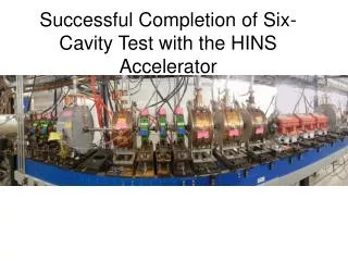
Tests of the bare cavity at FREIA
Self-Excited Loop (SEL) • no need for frequency tracking during turn-on or amplitude ramping • quickly bring up cavity gradient without running the tuners • free of electromechanical instability J.R. Delayen, “Phase and Amplitude Stabilization of Super-conducting resonators”, Ph.D. Thesis, Caltech (1978).
SC Resonator Generator driven configuration SEL
Unlocked Self-Excited Loop: FREIA test bench A perfect sinusoidal signal amplifier attenuator A signal from the cavity is sent back to the amplifier through the attenuator. The next step is to close the phase loop. cavity
Day 2, zoomed in view • Q-circle method: • Makes use of the NI system • Time-consuming (~10 hours per test) • but fully automated by Krish
Transmitted signal upon re-conditioning re-conditioning started 15 minutes later
Standard reflective type measurement forward VNA cavity reflected Reflection coefficient S11 Frequency
Self-excited loop cavity reflected signal limiter cavity forward drive signal 10 KHz span phase shifter amplifier The ratio of the reflected signals to the forward one gives S11
Microphonics at low and high power dissipated power
Quasi-static Lorentz Force Detuning The loop amplitude is modulated with a 10-sec period.
Quasi-static Lorentz Force Detuning cont’d The loop amplitude is modulated with a 20-secperiod. The 7.7 Hz resonance is suppressed and the overall microphonics level is reduced.
Quasi-static Lorentz force detuning: 20-sec Hz/(MV/m)^2
Cavity voltage and frequency modulation 3 Hz 3 Hz 100 Hz 100 Hz
Cavity voltage and frequency modulation cont’d 318 Hz 318 Hz 600 Hz 600 Hz
Transfer function of the dynamic Lorentz force detuning noise goes up because the cavity voltage modulation goes down
Guillaume’s simulations of the cavity mechanical modes Mode 3: 265 Hz Mode 1: 212 Hz Mode 5: 285Hz Mode 12: 396Hz