Download
1 / 31
310 likes | 398 Views
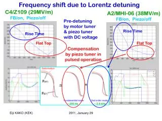
Beta .62 Triple Spoke Cavity Pressure Induced Frequency Shift. August 7, 2004. Outline. Slides 3 – 13 are the same as the previous analysis package dated 7-28-04

E N D
Beta .62 Triple Spoke Cavity Pressure Induced Frequency Shift August 7, 2004
Outline • Slides 3 – 13 are the same as the previous analysis package dated 7-28-04 • The model was then rebuilt to “clean up” legacy surfaces from previous geometry. This resulted in a shift in the results of about +4 to +5 kHz for cases with pressure. We are not sure why this is however the results for the baseline case (no pressure) agree exactly between models. The new model has been thoroughly checked and it looks good. • New results in this package are: • 24 radial stiffeners plus 4 longitudinal – slides 14-16 • 24 radial stiffeners plus 9 longitudinal – slides 17-18 • 24 radial stiffeners plus 17 longitudinal – slides 19-20 • 28 radial stiffeners and no longitudinal – slides 21-25 • 24 radial stiffeners plus 4 longitudinal PLUS 500 pounds inward force on each end flange – slides 26-29 • The 500 pounds is an approximation of the restoring force that the He vessel end-wall bellows generates on the flange. This was a quick way to look at the effect of reducing the stiffness of the bellows and/or the stiffness of the end wall. • Frequency Shift Results for All Cases – slide 30 Bellows Bellows Geometry Common to all Runs
Triple Spoke Model – Beta .62 – Radial stiffeners Boundary constraints 4 ux 4 uy 2 uz Pressure Load internal to Helium vessel 14.7 psi
Axial Displacements Helium assumed to be at 14.7 psi Properties evaluated at RT Axial Displacements inches
Radial Displacements - cavity Helium assumed to be at 14.7 psi Properties evaluated at RT Cavity Cavity Radial Displacements inches
Triple Spoke Model – Beta .62 16 radial stiffeners 1.25 “ Stiffener geometry and position from J. Fuerst Stiffener is 40º included angle, 1.25” high Stiffener spacing is 5.678” center to center End stiffeners
Triple Spoke Model – Beta .62 - 16 Radial Stiffeners Boundary constraints 4 ux 4 uy 2 uz Pressure Load internal to Helium vessel 14.7 psi
Axial Displacements Helium assumed to be at 14.7 psi Properties evaluated at RT Axial Displacements inches
Radial Displacements - cavity Helium assumed to be at 14.7 psi Properties evaluated at RT Cavity Cavity Radial Displacements inches
Triple Spoke Model – Beta .62 - 24 Radial Stiffeners Pressure Load internal to Helium vessel 14.7 psi Boundary constraints 4 ux 4 uy 2 uz Stiffener geometry and position MODIFIED Stiffener is 47.5º included angle, 1.25” high Stiffener spacing remains 5.678” center to center Extra stiffeners added – Now 6 per side NOTE: With stiffener at 47.5º included angle the distance between spacers azimuthally is approximately the same as the beta .50 Cavity (45º stiffeners on the beta .50).
Axial Displacements 24 Radial Stiffeners Helium assumed to be at 14.7 psi Properties evaluated at RT Cavity Cavity Axial Displacements inches
Radial Displacements - 24 Radial Stiffeners Radial Displacements inches
Triple Spoke Beta .62 RF Results • Result of a vessel without pressure Load • 342.12255 MHz • With 14.7 Psi internal to helium vessel and modified end stiffener • No radial stiffeners • 342.16890 MHz • Freq Shift +46.350 • With 14.7 Psi internal pressure and 16 added radial stiffeners • 342.14598 MHz • Freq Shift +23.43 KHz • With 14.7 Psi internal pressure and 24 added radial stiffeners • 342.13499 MHz • Freq Shift +12.44 KHz
Axial displacements 24 radial stiffeners and 4 longitudinal Axial Displacements inches
Radial displacements 24 radial stiffeners and 4 longitudinal
Radial displacements 24 radial stiffeners and 9 longitudinal
Axial displacements 24 radial stiffeners and 17 longitudinal
Radial displacements 24 radial stiffeners and 17 longitudinal
Layout for 28 Radial Stiffeners 1. Add one more 47.5º stiffener per side (28 total). 2. Reduce Stiffener Spacing to 4.542” center to center (spacing on beta .50 was 4.515”)
Triple Spoke Model – Beta .62 with 28 Radial Stiffeners Boundary constraints 4 ux 4 uy 2 uz Pressure Load internal to Helium vessel 14.7 psi 28 radial stiffeners
Axial Displacements - 28 Radial Stiffeners Helium assumed to be at 14.7 psi Properties evaluated at RT Axial Displacements inches
Axial Displacements - 28 Radial Stiffeners Helium assumed to be at 14.7 psi Properties evaluated at RT Cavity Axial Displacements inches
Radial Displacements - 28 Radial Stiffeners Radial Displacements inches
Axial Displacements – 24 radial stiff and 4 longitudinal with 500# load added to ends 500 lbs 500 lbs Axial Displacements inches
Axial Displacements – 24 radial stiff and 4 longitudinal with 500# load added to ends 500 lbs 500 lbs Axial Displacements inches
Radial Displacements – 24 radial stiff and 4 longitudinal with 500# load added to ends Radial Displacements inches
Stress Contours – 24 radial stiff and 4 longitudinal with 500# load added to ends Stresses OK von Mises stress psi
Triple Spoke Beta .62 RF Results – new model • Result of a vessel without pressure Load (Agrees exactly with previous model) • 342.12255 MHz • With 14.7 Psi internal to helium vessel - No radial or longitudinal stiffeners • 342.17276 MHz • Freq Shift +50.210 kHz • With 14.7 Psi internal pressure - 24 radial stiffeners and 4 longitudinal • 342.13961 MHz • Freq Shift +17.05 kHz • 342.12763 MHz WITH 500 lbs inward on each endwall • Freq Shift +5.08 kHz • With 14.7 Psi internal pressure - 24 radial stiffeners and 9 longitudinal • 342.13918 MHz • Freq Shift +16.63 kHz • With 14.7 Psi internal pressure - 24 radial stiffeners and 17 longitudinal • 342.13860 MHz • Freq Shift +16.05 kHz • With 14.7 Psi internal pressure - 28 radial stiffeners and no longitudinal • 342.13709 MHz • Freq Shift +14.54 kHz
Next Steps? • Increase span of radial stiffeners (see below) and offset • Decrease stiffness of endwall bellows – Can a standard formed bellows (with radial guides to support cavity) be used to reduce restoring force? • Reduce stiffness of Nb end wall stiffeners (machining not very desirable but possible) Stiffener Span Increased to 57.5º And Offset from 45º Lines