Download
1 / 21
210 likes | 324 Views
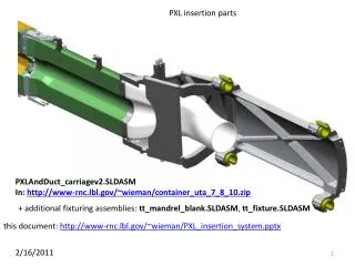
PXL Mechanical. Hinge rework in aluminum and carriage redesign Kinematic rework and analysis Insertion test - detailing and fabrication instructions Spatial Calibration. New carriage design. Low mass, reduced space usage. Analysis in seconds. Test of cable load support.

E N D
PXL Mechanical • Hinge rework in aluminum and carriage redesign • Kinematic rework and analysis • Insertion test - detailing and fabrication instructions • Spatial Calibration
New carriage design Low mass, reduced space usage
Analysis in seconds Test of cable load support
Hinge structure in aluminum, improved stability. Low mass, 2 mm thick - stable. Expanded air duct passage.
Cam guide FEE check 20 lb load, 20 micron deflection, yield – no problem
Kinematic mounts, cock and lock spring loaded contacts to define detector location when inserted
Joseph Silber Kinematic Mounts Insertion and Retraction Forces May 11, 2010 9
Offset, Radii • Horizontal offset makes manual analysis of design difficult. • R1 ≠ R2 contributes further to this. 11
Further considerations • Constraint surfaces are not C1 continuous, so contact conditions require some additional searching logic, and discontinuities in calculated forces are expected. • The combined assembly consists of two “top” mounts and one “bottom”. These effects must be calculated in phase with each other for summing up the forces. • Total insertion and retraction force differ in magnitude, due to non-conservative friction forces. • Friction forces differ depending on static versus dynamic. 12
Status • We now have a general code for analyzing kinematic constraints of arbitrary piecewise complexity. • Now use code to optimize the design. • Analysis of current design shows potential gains in: • smoothing the insertion and retraction force curves • eliminating the negative force condition (“suck-in”) • simplifying the offset and radius conditions of contacts 16
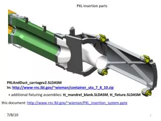
rail test system rail_test_system.SLDASM 5/3/2010 this document: http://www-rnc.lbl.gov/~wieman/Rail_test_system.pptx models: http://www-rnc.lbl.gov/~wieman/rail_test_system_05_03_10.zip 17
Example tolerance spec ±0.05 mm tolerances are to preserve glue bond thicknesses this and other 2 similar planes tolerances to chord and axis of ref cylinder: ±0.05 mm this plane perpendicular to a ref cylinder axis • line between • holes centered on • ref cylinder axis • to ±0.05 mm • separation tolerance • ±0.05 mm or match drilled • with butch_plate_single.SLDPRT • diameter tolerance: • +0.000 mm • 0.005 mm • for bullet insert press fit these and other similar holes diameter tolerance: ±0.005 mm for press fit with tooling balls, glue in OK if ends up sloppy grand_master.SLDPRT 19
Bob Connors Spiros Margetis Yifei Zhang development of spatial map 10 gm touch probe force touch probe 2-3 m (xyz) and visual 2-3 m (xy) 50 m (z) active volume: huge visual sub micron (xyz) repeatability 5 m accuracy over active volume no touch probe active volume: 30 in X 30 in X 12 in MEMOSTAR3, 30 m pitch
Visualization of touch probe data in solid works Coordinate Measuring Machine gives touch probe ball location plus a unit vector in the direction of the touch force. This figure shows ball location plus ball radius times unit vector. Michal and Xiangming have developed code for putting coordinate machine data into more convenient form