Download
1 / 19
190 likes | 263 Views
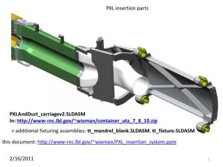
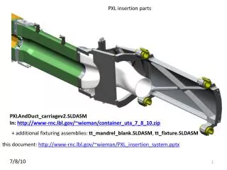
Fixturing operations for PXL. models: MSC.SLDASM MSC_fixtured.SLDASM rail_test_system.SLDASM. 2/24/2010. operations addressed:. PIT flange attachment PIT rail attachment Rail testing system PST flange attachment PST kinematic attachment SSD locating fixture

E N D
Fixturing operations for PXL models: MSC.SLDASM MSC_fixtured.SLDASM rail_test_system.SLDASM 2/24/2010
operations addressed: • PIT flange attachment • PIT rail attachment • Rail testing system • PST flange attachment • PST kinematic attachment • SSD locating fixture • Spatial mapping of the pixels with the Coordinate Measuring Machine (CMM)
PIT flange attachment • assemble PIT end plate fixture • load flanges on PIT and insert into the PIT end plate fixture • bond flanges (middle flange?) • cut holes for rail mounts • now ready for rail mounting
cut holes in PIT for rail supports • install cutting guide, cut 4 holes • flip guide, cut 4 more • rotate PIT 180 deg, repeat for 8 more holes
Bond rail supports apply glue and mount to rails with post passing through holes insert rails with rail holder fixture bonded rail support
keep track of which post goes with which pad remove post freeing rails and rail holder for removal • remove rails and rail holder • release rails from rail holder • remove PIT from end fixtures (can’t remove with rails in place) • reattach rails to PIT with correctly identified posts
rail tester rail_test_system.SLDASM (operation view)
tester rail attachment • Assemble PIT flange mounting plates • Assemble tester frame
install rail holder with rails, posts and bond pads removed cams are removed so that cross bars (not shown) coupling rails constrain the rotation angle in the guides spread glue attach post and bond pad
remove posts removing the posts allow that rails and rail holder to be removed. Rails without the rail holder can then be reattached to the rail tester by reinstalling the posts.
attach kinematic mounts to rail tester butch plate grand master with kinematic mounts • remove rails • mount butch plate • apply glue to cross arms and base plate • attach grand master to butch plate • after glue sets remove butch plate and separate rail tester from PIT end plates • reattach rails • tester is now complete • grand master can be detached from base plate for later use after testing is complete base plate attached to grand master cross arms
PST flange attachment • Assemble PST end plate fixture • load flanges on PST and insert into the PST end plate fixture • bond flanges • cut holes (fixture yet to be designed) • Now ready for attaching the kinematic mounts
PST kinematic mount attachment • remove east PST end plate • attach empty grand master to east PST end plate • attach PST end plate with grand master back on to the PST fixture east PST end plate grand master
kinematic mount • assemble kinematic mounts with bond feet • attach mount with feet to cross bar • apply adhesive adhesive
PST kinematic mount attachment • attach kinematic mounts to grand master by securing cross bar to grand master • allow setup and remove cross bars from feet and grand master • detach grand master from east PST end plate and support the grand master so that it does not load PST • Remove end plates and grand master • PST done
Summary of PST kinematic attachment • remove east PST end plate • attach empty grand master to east PST end plate • attach PST end plate with grand master back on to the PST fixture • assemble kinematic mounts with bond feet • attach mount with feet to cross bar • apply adhesive • attach kinematic mounts to grand master by securing cross bar to grand master • allow setup and remove cross bars from feet and grand master • detach grand master from east PST end plate and support the grand master so that it does not load PST • Remove end plates and grand master • PST done
OSC fixture • The PIT fixture will also be used for the OSC since the OSC and PIT are the same diameter. The base plate will be changed to set the correct length • fixture used for placing the OSC flanges • flats and reference groves used to position SSD supports. Up to 6 ladder supports can be installed at one setting. The OSC is rotated in the fixture by 180 deg to do the remaining attachments.
Coordinate Measuring Machine (CMM) configuration The grand master fixture is also used to support the detector halves in the CMM for doing the spatial map of the pixels. The fixture is supported in the CMM with 3 point support on the tooling balls for all the required angular positions. The relative mapping of all the tooling balls provides the required cross referencing of all the angular positions. The same kinematic supports are used here as are used in the STAR detector installation.