Download
1 / 42
420 likes | 525 Views
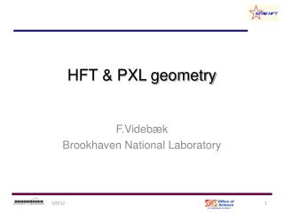
HFT PXL Mechanical July 2010. Howard Wieman LBNL. Topics. PXL reminder Tools for probe testing thinned 50 m chips PXL support with rapid detector swapping. Pixel geometry. These inner two layers provide the projection precision. End view. 8 cm radius. 20 cm. 2.5 cm radius.

E N D
HFT PXL MechanicalJuly 2010 Howard Wieman LBNL
Topics • PXL reminder • Tools for probe testing thinned 50 m chips • PXL support with rapid detector swapping
Pixel geometry. These inner two layers provide the projection precision End view 8 cm radius 20 cm 2.5 cm radius Inner layer Outer layer coverage +-1 One of two half cylinders total 40 ladders
Some pixel features and specifications critical and difficult more than a factor of 3 better than other vertex detectors (ATLAS, ALICE and PHENIX)
Thinned MAPS performance • Thinner and smaller pixels than a hybrid pixel detector • Accumulates statistics for 0.5 GeV D0 36 times faster than a hybrid • 200 times faster for 1.5 GeV
Mechanics Previously Reported • Pointing requirements and a design to satisfy low multiple coulomb scattering plus high stability • Detector assembly • Vibration tests • Cooling tests (Michal Szelezniak)
Vacuum chuck for probe station handling of thinned silicon needed new mechanics for probe testing
PXL support designed with emphasis on rapid replacement • Motivation – most vertex detectors failed to produce because they could not be easily accessed and repaired • Report on design progress on insertion and alignment • more involved mechanical design now practical with modern 3D CAD software that was not available for the original STAR design • Designs guided by Eric Anderssen
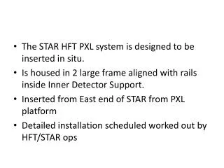
HFT PXL – installation design • a well controlled method for installation of the pixel detector has been developed with emphasis on ease of operation and avoidance of detector risk • The PXL assembly will be enclosed in a carrying box that is equipped for transfer of the detector assembly into the PXL support tube • Once inserted on tracks the detector is guided into position locking kinematic mounts
maneuvering the detector into the IP with cams and rails PST PIT
initial open position clears the wide region of the beam pipe partially closed to fit into PST operating position closed around the beam pipe
top two kinematic mounts bottom not complete
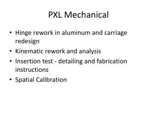
hinge and carriage machined aluminum 2 mm thick contoured to form light rigid structures cam follower rail bearings cooling air hose adapter rapid prototype 1 mm thick carbon composite support tube and cooling air duct
testing of parts with CAD tools - work directly within CAD program 20 lb extended load for cables 0.4 mm displacement • less than 10 minutes to setup problem with constraints and loads • few seconds to mesh • 12 seconds to solve
overlay of multi functional fixtures • construct insertion test system • bond flanges on carbon composite support tubes • cut holes in support tubes • bond rails into support tubes • bond kinematic mounts into support tubes • support detector in kinematic mounts for spatial mapping in coordinate measuring machine • position SSD mounts on support tube for bonding
Coordinate Measuring Machine (CMM) configuration The grand master fixture is also used to support the detector halves in the CMM for doing the spatial map of the pixels. The fixture is supported in the CMM with 3 point support on the tooling balls for all the required angular positions. The relative mapping of all the tooling balls provides the required cross referencing of all the angular positions. The same kinematic supports are used here as are used in the STAR detector installation.
Status of parts • Models and 60 pages of power point instructions submitted to LBNL main shop and University of Texas Austin machine shop – fabrication expected to start shortly
PIT flange attachment • assemble PIT end plate fixture • load flanges on PIT and insert into the PIT end plate fixture • bond flanges (middle flange?) • cut holes for rail mounts • ready for rail mounting
cut holes in PIT for rail supports • install cutting guide, cut 4 holes • flip guide, cut 4 more • rotate PIT 180 deg, repeat for 8 more holes
Bond rail supports apply glue and mount to rails with post passing through holes insert rails with rail holder fixture bonded rail support
keep track of which post goes with which pad remove post freeing rails and rail holder for removal • remove rails and rail holder • release rails from rail holder • remove PIT from end fixtures (can’t remove with rails in place) • reattach rails to PIT with correctly identified posts
rail tester rail_test_system.SLDASM (operation view)
tester rail attachment • Assemble PIT flange mounting plates • Assemble tester frame
install rail holder with rails, posts and bond pads removed cams are removed so that cross bars (not shown) coupling rails constrain the rotation angle in the guides spread glue attach post and bond pad
remove posts removing the posts allow that rails and rail holder to be removed. Rails without the rail holder can then be reattached to the rail tester by reinstalling the posts.
attach kinematic mounts to rail tester butch plate grand master with kinematic mounts • remove rails • mount butch plate • apply glue to cross arms and base plate • attach grand master to butch plate • after glue sets remove butch plate and separate rail tester from PIT end plates • reattach rails • tester is now complete • grand master can be detached from base plate for later use after testing is complete base plate attached to grand master cross arms
PST flange attachment • Assemble PST end plate fixture • load flanges on PST and insert into the PST end plate fixture • bond flanges • cut holes (fixture yet to be designed) • Now ready for attaching the kinematic mounts
PST kinematic mount attachment • remove east PST end plate • attach empty grand master to east PST end plate • attach PST end plate with grand master back on to the PST fixture east PST end plate grand master
kinematic mount • assemble kinematic mounts with bond feet • attach mount with feet to cross bar • apply adhesive adhesive
PST kinematic mount attachment • attach kinematic mounts to grand master by securing cross bar to grand master • allow setup and remove cross bars from feet and grand master • detach grand master from east PST end plate and support the grand master so that it does not load PST • Remove end plates and grand master • PST done
Summary of PST kinematic attachment • remove east PST end plate • attach empty grand master to east PST end plate • attach PST end plate with grand master back on to the PST fixture • assemble kinematic mounts with bond feet • attach mount with feet to cross bar • apply adhesive • attach kinematic mounts to grand master by securing cross bar to grand master • allow setup and remove cross bars from feet and grand master • detach grand master from east PST end plate and support the grand master so that it does not load PST • Remove end plates and grand master • PST done
OSC fixture • The PIT fixture will also be used for the OSC since the OSC and PIT are the same diameter. The base plate will be changed to set the correct length • fixture used for placing the OSC flanges • flats and reference groves used to position SSD supports. Up to 6 ladder supports can be installed at one setting. The OSC is rotated in the fixture by 180 deg to do the remaining attachments.