Download
1 / 45
450 likes | 455 Views
This lecture covers the fundamentals of system modeling, including different perspectives and UML diagram types. Topics include context models, interaction models, structural models, and behavioral models.

E N D
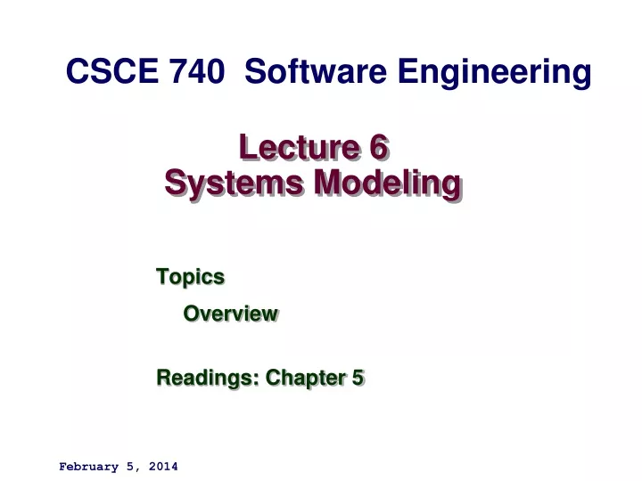
Lecture 6Systems Modeling CSCE 740 Software Engineering • Topics • Overview • Readings: Chapter 5 February 5, 2014
Last Time • Requirements • More Ruby • Major Items on last times slides not covered • (Lec 05 slide 32- • New from Chapter 5 – System Modeling • Rational Unified Process (Lec 02 slides 45-) • Functional and non-functional requirements • The software requirements document • Requirements specification • Next Time: System Modeling
Dropbox • Department Home page for Link • Login with Engr(CEC) domain credentials. • CSCE 740-001
Chapter 5 System modeling Topics covered • Context models • Interaction models • Structural models • Behavioral models • Model-driven engineering
Chapter 5 System modeling System modeling • System modeling is the process of developing abstract models of a system, with each model presenting a different view or perspective of that system. • System modeling has now come to mean representing a system using some kind of graphical notation, which is now almost always based on notations in the Unified Modeling Language (UML). • System modelling helps the analyst to understand the functionality of the system and models are used to communicate with customers. • HW2.1 What is the best Free UML too?
Chapter 5 System modeling Existing and planned system models • Models of new systems and existing systems are used during requirements. • In a model-driven engineering process, it is possible to generate a complete or partial system implementation from the system model.
Chapter 5 System modeling System perspectives • An external perspective, where you model the context or environment of the system. • An interaction perspective, where you model the interactions between a system and its environment, or between the components of a system. • A structural perspective, where you model the organization of a system or the structure of the data that is processed by the system. • A behavioral perspective, where you model the dynamic behavior of the system and how it responds to events.
Chapter 5 System modeling UML diagram types • Activity diagrams, which show the activities involved in a process or in data processing . • Use case diagrams, which show the interactions between a system and its environment. • Sequence diagrams, which show interactions between actors and the system and between system components. • Class diagrams, which show the object classes in the system and the associations between these classes. • State diagrams, which show how the system reacts to internal and external events. • http://en.wikipedia.org/wiki/A_picture_is_worth_a_thousand_words
Chapter 5 System modeling The context of the MHC-PMS http://www.cs.st-andrews.ac.uk/~ifs/Teaching/MScSysEng-2004/Notes/MHCPMSCaseStudy.pdf
Chapter 5 System modeling Process model of involuntary detention
Chapter 5 System modeling Use case modeling • Use cases were developed originally to support requirements elicitation and now incorporated into the UML. • Each use case represents a discrete task that involves external interaction with a system. • Actors in a use case may be people or other systems. • Represented diagrammatically to provide an overview of the use case and in a more detailed textual form.
Chapter 5 System modeling Transfer-data use case • A use case in the MHC-PMS
Chapter 5 System modeling Tabular description of the ‘Transfer data’ use-case
Chapter 5 System modeling Use cases in the MHC-PMS involving the role ‘Medical Receptionist’
Chapter 5 System modeling Sequence diagrams • Sequence diagrams are part of the UML and are used to model the interactions between the actors and the objects within a system. • A sequence diagram shows the sequence of interactions that take place during a particular use case or use case instance. • The objects and actors involved are listed along the top of the diagram, with a dotted line drawn vertically from these. • Interactions between objects are indicated by annotated arrows.
Chapter 5 System modeling Sequence diagram for View patient information
Chapter 5 System modeling Sequence diagram for Transfer Data
Chapter 5 System modeling Structural models • Structural models of software display the organization of a system in terms of the components that make up that system and their relationships. • Architectural diagrams • Class diagrams
Chapter 5 System modeling Class diagrams • Class diagrams are used when developing an object-oriented system model to show the classes in a system and the associations between these classes. • An object class can be thought of as a general definition of one kind of system object. • An association is a link between classes that indicates that there is some relationship between these classes. • When you are developing models during the early stages of the software engineering process, objects represent something in the real world, such as a patient, a prescription, doctor, etc.
Chapter 5 System modeling Classes and associations in the MHC-PMS
Chapter 5 System modeling The Consultation class
Chapter 5 System modeling Key points • A model is an abstract view of a system that ignores system details. Complementary system models can be developed to show the system’s context, interactions, structure and behaviour. • Context models show how a system that is being modeled is positioned in an environment with other systems and processes. • Use case diagrams and sequence diagrams are used to describe the interactions between users and systems in the system being designed. Use cases describe interactions between a system and external actors; sequence diagrams add more information to these by showing interactions between system objects. • Structural models show the organization and architecture of a system. Class diagrams are used to define the static structure of classes in a system and their associations.
Chapter 5 System modeling A generalization hierarchy
Chapter 5 System modeling A generalization hierarchy with added detail
Chapter 5 System modeling Object class aggregation models • An aggregation model shows how classes that are collections are composed of other classes. • Aggregation models are similar to the part-of relationship in semantic data models.
Chapter 5 System modeling The aggregation association
Chapter 5 System modeling Behavioral models • Behavioral models are models of the dynamic behavior of a system as it is executing. They show what happens or what is supposed to happen when a system responds to a stimulus from its environment. • You can think of these stimuli as being of two types: • Data Some data arrives that has to be processed by the system. • Events Some event happens that triggers system processing. Events may have associated data, although this is not always the case.
Chapter 5 System modeling Data-driven modeling • Many business systems are data-processing systems that are primarily driven by data. They are controlled by the data input to the system, with relatively little external event processing. • Data-driven models show the sequence of actions involved in processing input data and generating an associated output.
Chapter 5 System modeling An activity model of the insulin pump’s operation
Chapter 5 System modeling Order processing
Chapter 5 System modeling Event-driven modeling • Real-time systems are often event-driven, with minimal data processing. For example, a landline phone switching system responds to events such as ‘receiver off hook’ bygenerating a dial tone. • Event-driven modeling shows how a system responds to external and internal events. • It is based on the assumption that a system has a finite number of states and that events (stimuli) may cause a transition from one state to another.
Chapter 5 System modeling State machine models • These model the behaviour of the system in response to external and internal events. • They show the system’s responses to stimuli so are often used for modelling real-time systems. • State machine models show system states as nodes and events as arcs between these nodes. When an event occurs, the system moves from one state to another. • Statecharts are an integral part of the UML and are used to represent state machine models.
Chapter 5 System modeling State diagram of a microwave oven
Chapter 5 System modeling States and stimuli for the microwave oven (a)
Chapter 5 System modeling States and stimuli for the microwave oven (b)
Chapter 5 System modeling Microwave oven operation
Chapter 5 System modeling Model-driven engineering • Model-driven engineering (MDE) is an approach to software development where models rather than programs are the principal outputs of the development process. • The programs that execute on a hardware/software platform are then generated automatically from the models. • Proponents of MDE argue that this raises the level of abstraction in software engineering so that engineers no longer have to be concerned with programming language details or the specifics of execution platforms.
Chapter 5 System modeling Usage of model-driven engineering • Model-driven engineering is still at an early stage of development, and it is unclear whether or not it will have a significant effect on software engineering practice. • Pros • Allows systems to be considered at higher levels of abstraction • Generating code automatically means that it is cheaper to adapt systems to new platforms. • Cons • Models for abstraction and not necessarily right for implementation. • Savings from generating code may be outweighed by the costs of developing translators for new platforms.
Chapter 5 System modeling Model driven architecture • Model-driven architecture (MDA) was the precursor of more general model-driven engineering • MDA is a model-focused approach to software design and implementation that uses a subset of UML models to describe a system. • Models at different levels of abstraction are created. From a high-level, platform independent model, it is possible, in principle, to generate a working program without manual intervention.
Chapter 5 System modeling Types of model • A computation independent model (CIM) • These model the important domain abstractions used in a system. CIMs are sometimes called domain models. • A platform independent model (PIM) • These model the operation of the system without reference to its implementation. The PIM is usually described using UML models that show the static system structure and how it responds to external and internal events. • Platform specific models (PSM) • These are transformations of the platform-independent model with a separate PSM for each application platform. In principle, there may be layers of PSM, with each layer adding some platform-specific detail.
Chapter 5 System modeling Agile methods and MDA • The developers of MDA claim that it is intended to support an iterative approach to development and so can be used within agile methods. • The notion of extensive up-front modeling contradicts the fundamental ideas in the agile manifesto and I suspect that few agile developers feel comfortable with model-driven engineering. • If transformations can be completely automated and a complete program generated from a PIM, then, in principle, MDA could be used in an agile development process as no separate coding would be required.
Chapter 5 System modeling Executable UML • The fundamental notion behind model-driven engineering is that completely automated transformation of models to code should be possible. • This is possible using a subset of UML 2, called Executable UML or xUML.
Chapter 5 System modeling Features of executable UML • To create an executable subset of UML, the number of model types has therefore been dramatically reduced to these 3 key types: • Domain models that identify the principal concerns in a system. They are defined using UML class diagrams and include objects, attributes and associations. • Class models in which classes are defined, along with their attributes and operations. • State models in which a state diagram is associated with each class and is used to describe the life cycle of the class. • The dynamic behaviour of the system may be specified declaratively using the object constraint language (OCL), or may be expressed using UML’s action language.
Chapter 5 System modeling Key points • Behavioral models are used to describe the dynamic behavior of an executing system. This behavior can be modeled from the perspective of the data processed by the system, or by the events that stimulate responses from a system. • Activity diagrams may be used to model the processing of data, where each activity represents one process step. • State diagrams are used to model a system’s behavior in response to internal or external events. • Model-driven engineering is an approach to software development in which a system is represented as a set of models that can be automatically transformed to executable code.
HW 2 – Due Tuesday September 18 • HW2.1 What is the best Free UML too? • Read MHC-PMS document – paragraph summary emphasizing diagrams • http://www.cs.st-andrews.ac.uk/~ifs/Teaching/MScSysEng-2004/Notes/MHCPMSCaseStudy.pdf • Ruby program to read web page and display links. • Google – ruby url reader open-uri (2005) • http://stdlib.rubyonrails.org/libdoc/open-uri/rdoc/index.html • Made any progress since then? REXML maybe? URI maybe?