Download
1 / 30
300 likes | 426 Views
The Object-oriented Paradigm and The Unified Modeling Language (UML). Problems of software development. "problems" of software development (review): **conceptual integrity **incremental build, progressive refinement **large projects "differ" from small ones

E N D
The Object-oriented Paradigm and The Unified Modeling Language (UML)
Problems of software development • "problems" of software development (review): • **conceptual integrity • **incremental build, progressive refinement • **large projects "differ" from small ones • programming paradigms (1950’s-present): attempts to deal effectively with these problems, make software easier to develop and to maintain
Languages and design methodology Computer Language / Design Methodology: brief history: 1950's:unstructured, no information hiding--”spaghetti” code, GOTO, flowcharts --machine code --assembly lang. --FORTRAN, LISP (Algol; COBOL) 1980’s: structured, top-down design (“3 basic control structures, no GOTO”), modularity --Pascal --(C) --Ada 1990’s: encapsulation, information-hiding, reuse, hardware/software codesign (from simulation languages developed much earlier, e.g., Modula, simula) --C++ --Java 2000’s: info hiding; web languages; environments encapsulating multiple languages, styles --.NET, C# --Python --MATLAB, Mathematica, Labview, …
A Brief History: Computer Hardware, Computer Languages, Design Techniques 1950's:unstructured, no information hiding--”spaghetti” code, GOTO, flowcharts --machine code --assembly lang. --FORTRAN, LISP (Algol; COBOL) 1970s,1980s: structured, top-down design (“3 basic control structures, no GOTO”), modularity --Pascal, C, PL/I, Ada 1990’s: encapsulation, information-hiding, reuse, hardware/software codesign (from simulation languages developed much earlier, e.g., Modula, simula) --C++, Java 2000’s: info hiding; web languages; environments encapsulating multiple languages, styles --.NET, C#, Python, Perl, MATLAB, Mathematica, Labview, … Early machines—large, central (Eniac) Supercomputers, “Minicomputers”, PCs, multiuser machines, PICs Beowulf clusters, Spread of the Internet “Ubiquitous computing”, laptops,. Personal communication devices, multicore processors, GPUs wpclipart.com chilton-computing.org.uk http://en.wikipedia.org/wiki/PIC _microcontroller#History techxav.com cse.mtu.edu visual.merriam-webster.com
OO class • Important basic OO concepts: • class: encapsulates data • structure (object) and associated methods (functions) • these may be declared public / private / protected • appropriate uses: • public: pass info to object or request info about object • (use "messages") (can be used by anyone) • private: modify object (can be used in class or by “friends”) • protected: for descendants (in class or by derived class and “friends”)
Record/class traditional: record (struct): functions to use or modify this record can be anywhere in the program OO: class concept supports encapsulation, information hiding OO Prog. DATA DATA DATA DATA DATA DATA DATA Procedural Prog.
Ex: Object data structures: A. Base class B. Derived class X Y Z W X Y Z A. B. Inheritance Useful OO techniques: Inheritance: ex: in a program modeling an ecosystem, we might have the relationships: wolf is carnivore; sheep is herbivore; grass is plant carnivore is animal; herbivore is animal animal is organism; plant is organism here the base class “organism” holds data fields which apply to all organisms, e.g., amount of water needed to survive two derived classes, plant and animal, hold information specific to each of these types of organisms, e.g., kind of soil preferred by plant the animal class also has two derived classes, wolf and sheep Inheritance allows the collection of common attributes and methods in "base" class and inclusion of more specific attributes and methods in derived classes
Polymorphism: base class can define a “virtual” function; appropriate versions of this function can be instantiated in each derived class (e.g., "draw" in the base class of graphical objects can have its own specific meaning for rectangles, lines, ellipses) Overloading: ex: cin >> num1; >> is overloaded "shift” ex: “+” can be overloaded to allow the addition of two vectors ex: a function name can be overloaded to apply to more than one situation; e.g., a constructor can be defined one way if initial values are given and a different way if initial values are not given Polymorphism and overloading
Templates Templates: example: template <class T> T method1 (T x) ….. can be specialized: int method1 (int x) float method1 (float y) usertype method1 (usertype a) templates promote reuse
Separate compilation • Separate compilation: • Typically, an object-oriented program can be broken into three sets of components: • definitions and prototypes (text files, “header files”) • implementations (compiled--source code need not be available to user) • application program--uses the classes defined in header files and supported by the implementation files • This strategy promotes reuse and information hiding
Misuse of object-oriented paradigm Note: no paradigm is misuse-proof
Developing an OO project: we will use UML (subset) determine specifications: use cases [scenario: instance of use case; concrete informal description of 1 feature; enhances understanding of use case] determine classes and connections (static behavior): ER or class diagrams CRC cards model dynamic behavior: interaction (object message) diagrams activity diagrams state diagrams sequence diagrams Using OO & UML in quarter project
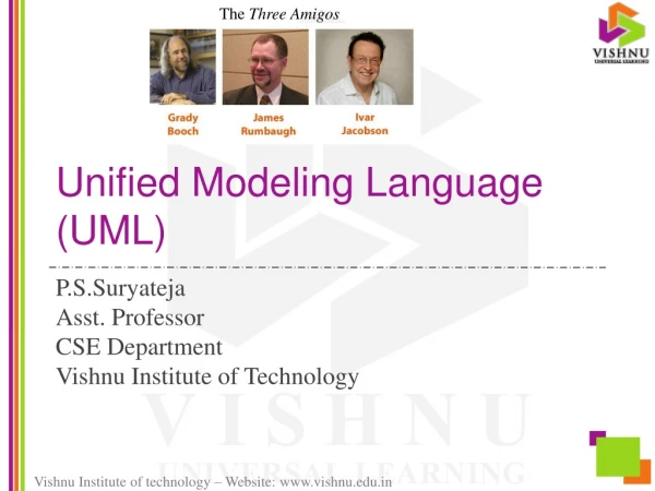
UML: stands for "unified modeling language” unifies methods of Booch, Rumbaugh (OMT or Object Modeling Technique), and Jacobson (OOSE or Object-Oriented Software Engineering) mainly a modeling language, not a complete development method Early versions -- second half of the 90's Not all methods we will use are officially part of the UML description (e.g., CRC cards) There exist many versions of UML—syntax may have slight differences among versions—be aware of this as you read and work on homework and projects UML: a language for specifying and designing an OO project
USE CASES: a part of the ”Unified Modeling Language" (UML) which we will use for requirements analysis and specification each identifies a way the system will be used and the "actors" (people or devices) that will use it (an interaction between the user and the system) each use case should capture some user-visible function and achieve some discrete goal for the user an actual user can have many actor roles in these use cases an instance of a use case is usually called a "scenario” Use case will typically have graphical & verbal forms Use cases
Example: cellular network place and receive calls use case (based on Booch, Rumbaugh, and Jacobson, The Unified Modeling Language User Guide) Example use case Text description --Use case name (cellular network place and receive calls) --Participating actors (cellular network and human user) --Flow of events (network or user accesses network to use its functionality) --Entry condition(s) (user accesses network using device or password) --Exit condition(s) (call completed lost or network busy) --Quality requirements (speed, service quality) --Open issues (for future versions, e.g.) System boundary Use case diagram—summarizes, provides system overview Text description—gives important details
use case Text description: Use case name Participating actors Flow of events Entry condition(s) Exit condition(s) Quality requirements
Encounters an error condition Arms/disarms system Responds to alarm event Use case—detailed example (Pressman) • Example: “SAFEHOME” system (Pressman) • Use case: InitiateMonitoring • (Pressman text categories: • Primary actor (1) • Goal in context (2) • Preconditions (3) • Trigger (4) • Scenario (5) • Exceptions (6) • Priority (system development) (7) • When available (8) • Frequency of use (9) • Channel to actor (10) • Secondary actors (11) • Channels to secondary actors (12) • Open issues (13) ) Homeowner Accesses system via internet Sensors System administrator Reconfigures sensors and related system features Pressman, p. 163, Figure 7.3
Use case—detailed example (Pressman) • Example: “SAFEHOME” system (Pressman) • Use case name:InitiateMonitoring • Participating actors: homeowner, technicians, sensors • Flow of events (homeowner): • --Homeowner wants to set the system when the homeowner leaves house or remains in house • --Homeowner observes control panel • --Homeowner enters password • --Homeowner selects “stay” or “away” • --Homeowner observes that read alarm light has come on, indicating the system is armed
Use detailed example (Pressman)--continued • Entry condition(s) • Homeowner decides to set control panel • Exit condition(s) • Control panel is not ready; homeowner must check all sensors and reset them if necessary • Control panel indicates incorrect password (one beep)—homeowner enters correct password • Password not recognized—must contact monitoring and response subsystem to reprogram password • Stay selected: control panel beeps twice and lights stay light; perimeter sensors are activated • Away selected: control panel beeps three times and lights away light; all sensors are activated
Use case—detailed example (Pressman) • Quality requirements: • Control panel may display additional text messages • time the homeowner has to enter the password from the time the first key is pressed • Ability to activate the system without the use of a password or with an abbreviated password • Ability to deactivate the system before it actually activates
<<include>> A C B <<include>> <<extend>> D F E <<extend>> Use case additions—simplifications of use case descriptions • A. Include: one use case includes another in its flow of events (cases A and B both include case C) • Example: report a fire: both “open incident” and “send fire trucks” include the use case “view city map” • Extend: extend one use case to include additional behavior (cases D and E are extensions of case F) • Example: ConnectionDown between two emergency responders is a “special case” of Reportemergency but it can use the basic functionality of ReportEmergency
Use case additions • C. Inheritance: one use case specializes the more general behavior of another G and H specialize behavior of J) • Note: use case inheritance is BEHAVIORAL or FUNCTIONAL inheritance • Standard OO inheritance is STRUCTURAL inheritance G J Authenticate with password authenticate H Authenticate with card
Use case continued Examples: what would be a use case for: vending machine user university student management system (e.g., student changes registration) Use case name Participating actors Flow of events Entry condition Exit condition Quality requirements
System Tests • TESTING at the system level: • Use cases can form a basis for system acceptance tests • For each use case: • Develop one or more system tests to confirm that the use case requirements will be satisfied • Add explicit test values as soon as possible during design phase • These tests are now specifically tied to the use case and will be used as the top level acceptance tests • Do not forget use cases / tests for performance and usability requirements (these may be qualitative as well as quantitative)
Requirements Specifications ….. Use cases, tests classes, … Requirements must be: --complete --consistent --unambiguous --correct
Another way to organize requirements (text)--FURPS: Functional requirements: *F—functionality Nonfunctional requirements: “Quality”: *U—Usability *R—Reliability (Dependability—reliability, robustness, safety) *P—Performance *S—Supportability “Constraints”: *implementation requirements Operations requirements, packaging requirements, legal requirements * = important this quarter
Steps to turn requirements into specifications: --identify actors --identify scenarios (specific examples of use cases) --identify use cases --refine use cases as appropriate (extends / includes)—don’t overdo this --identify relationships among actors and use cases --can now begin to identify objects needed ( design) --also need to identify nonfunctional requirements
Use case writing guide (p. 137 of text): --each use case should be traceable to requirements --name should be a verb phrase to indicate user goal --actor names should be noun phrases --system boundary needs to be clearly defined --use active voice in describing flow of events, to make clear who does what --make sure the flow of events describes a complete user transaction ---if there is a dependence among steps, this needs to be made clear --describe exceptions separately --DO NOT describe the user interface to the system, only functions --DO NOT make the use case too long—use extends, includes instead --as you develop use cases, develop associated tests
Example—bank simulation (Horstmann) Horstmann, Mastering Object-Oriented Design in C++, Wiley, 1995 Teller 1 Teller 2 Customer 3 Customer 2 Customer 1 Teller 3 Teller 4
Use Cases--Bank Goal: Develop a tool to simulate the bank to decide on optimal values for number of tellers, number of customer queues, etc. Use cases?