Download
1 / 22
220 likes | 475 Views
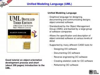
UML Unified Modeling Language. What is UML?. Unified Modeling Language (UML) is a standardized, general-purpose modeling language in the field of software engineering.

E N D
What is UML? • Unified Modeling Language (UML) is a standardized, general-purpose modeling language in the field of software engineering. • The Unified Modeling Language includes a set of graphic notation techniques to create visual models of object-oriented software-intensive systems.
UML diagrams represent two different views of a system model • Static (or structural) view: It emphasizes on the static structure of the system using objects, attributes, operations and relationships. 2. Dynamic (or behavioral) view: It emphasizes on the dynamic behavior of the system by showing collaborations among objects and changes to the internal states of objects.
Class Diagram • The class diagram is the main building block of object oriented modeling. • It is used both for general conceptual modeling of the systematics of the application and for detailed modeling translating the models into programming code. • Class diagrams can also be used for data modeling.
Components of Class Diagram • Class or Entity • Relationship/Association • Attributes
Classes • The classes in a class diagram represent both the main objects, interactions in the application and the classes to be programmed. • In the diagram, classes are represented with boxes which contain three parts: • The upper part holds the name of the class • The middle part contains the attributes of the class • The bottom part gives the methods or operations the class can take or undertake
Relationships or Association • An association represents a family of links. • Binary associations (with two ends) are normally represented as a line. • An association can be named, and the ends of an association can be adorned with role names, ownership indicators, multiplicity, visibility, and other properties.
There are four different types of association: bi-directional, uni-directional, Aggregation (includes Composition aggregation) and Reflexive. • Bi-directional and uni-directional associations are the most common.
Aggregation • Aggregation is a variant of the "has a" or association relationship; aggregation is more specific than association. • It is an association that represents a part-whole or part-of relationship. • Aggregation can occur when a class is a collection or container of other classes, but where the contained classes do not have a strong life cycle dependency on the container—essentially, if the container is destroyed, its contents are not.
Composition • Composition is a stronger variant of the "owns a" or association relationship; composition is more specific than aggregation. • Composition usually has a strong life cycle dependency between instances of the container class and instances of the contained class(es): If the container is destroyed, normally every instance that it contains is destroyed as well
Generalization • The Generalization relationship ("is a") indicates that one of the two related classes (the subclass) is considered to be a specialized form of the other (the super type) and superclass is considered as 'Generalization' of subclass.
Tables and Columns • A table is a set of data elements (values) that is organized using a model of vertical columns (which are identified by their name) and horizontal rows, the cell being the unit where a row and column intersect. • An attribute(Column) is a specification that defines a property of a table.
Keys • In an entity relationship diagram of a data model, one or more unique keys may be declared for each data entity. Each unique key is composed from one or more data attributes of that data entity. • In a relational database, a "Primary Key" is a key that uniquely defines the characteristics of each row (also known as record or tuple). • A table can have at most one primary key, but more than one unique key.
Primary Key Stereotype • We can Indicate a primary key in a table using <<PK>> stereotype. • Which looks something like this
Summary • Class Names = Table Names in UML • Object Names = Attribute/Column Names in UML • Use association to indicate relation between tables • Use <<PK>> Stereotype to indicate primary key.