Download

1 / 19
190 likes | 339 Views
Unified Modeling Language. What is it and why do I need to know. What is UML. OMG defines UML like this

E N D
Unified Modeling Language What is it and why do I need to know
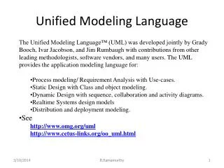
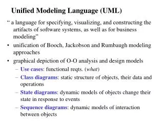
What is UML • OMG defines UML like this • “The Unified modeling language (UML) is a graphical language for visualizing, specifying, constructing, and documenting the artifacts of a software-intensive system. The UML offers a standard way to write a system’s blueprints, including conceptual things such as business process and system functions as well as concrete things such as programming language statements, database schemas, and reusable software components.”
History of UML • Late 20th century “method wars” • Number of modeling languages • Many overlapping languages • The “three amigos” emerge at Rational • Booch, OMT, and OOSE methods merge • Result is RUP and UML • Standardized under OMG • UML 0.9 release 1996, V1.0 submitted to OMG in 1997, revised to V1.1 later same year
Problem Domain Models • Use Case Model • Collaboration (Interaction) Model • Dynamic Model • Class (Logical) Model • Physical Component Model • Physical Deployment Model
Defining User Requirements Discovering the use cases
Use Case Model • Use cases define how a user (human or non-human) will use the system • Components • Actors • Use Cases • Relationships
An Actor Uses the System • Any external entity that makes use of the system • A human user • An external software or hardware component that makes use of the system • For example – POS would an EZ-Views actor
Use Case Defines an Activity • Each use case is a single activity • Log on • Create order • Use cases interact with other entities to define the features of the system
Relationships • Represented by lines and arrows on the diagram • Examples: • Uses • Extends and includes • Flow (of data or control) • Can be adorned with other descriptive information
Attributes • Description – general text about the entity • Responsibilities – what it must do, the heart of the functional spec • Constraints – limitations, either before, after or throughout an activity • Scenarios – text descriptions of the flow of events
Collaboration Model How entities interact to get the job done
Pieces of the Diagram • More than just actors and use cases • Physical entities, such as a web page • Relationships show how each piece is used.
Dynamic Model Showing the system in motion
Logical Model Fleshing out the design
Component Model Packaging the entities
Deployment Model How will we deliver it?
Questions • References • www.sparxsystems.com.au • UML Distilled