Download
1 / 28
280 likes | 287 Views
Design Issues for a 50W VHF/UHF Solid State RF Power Amplifier. Carl Luetzelschwab K9LA k9la@arrl.net http://k9la.us thanks WWROF (wwrof.org). Who Is K9LA?. First licensed in October 1961 as WN9AVT Selected K9LA in 1977 Enjoy propagation, DX, contests, antennas, vintage rigs

E N D
Design Issues for a 50W VHF/UHF Solid State RF Power Amplifier Carl Luetzelschwab K9LA k9la@arrl.net http://k9la.us thanks WWROF (wwrof.org) WWROF Webinar K9LA Nov 2015
Who Is K9LA? • First licensed in October 1961 as WN9AVT • Selected K9LA in 1977 • Enjoy propagation, DX, contests, antennas, vintage rigs • RF design engineer by profession (mostly RF power amplifiers) • BSEE 1969 and MSEE 1972 from Purdue University • Motorola Land Mobile 1974 to 1988 (Schaumburg and Fort Worth) • FM Power Amplifiers from 30 MHz to 512 MHz at 30 W to 100 W • Patent US4251784 Apparatus for Parallel Combining An Odd Number of Semiconductor Devices • Raytheon (formerly Magnavox) 1988 to Oct 2013 (Fort Wayne) • Power Amplifiers from 30 MHz to 2 GHz and from 10 W to 1 KW • Constant envelope waveforms (for example, FM) and non-constant envelope waveforms (for example, OFDM) • Patent 20040100341 MEMS-Tuned High-Power High-Efficiency Wide-Bandwidth Power Amplifier WWROF Webinar K9LA Nov 2015
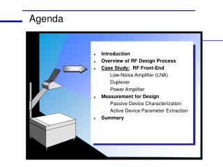
Introduction • A linear RF power amplifier (PA) takes a little signal and makes it bigger without losing fidelity theoretically! • This presentation discusses several design issues for a very broadband 50 Watt power amplifier • This presentation is not a construction project • This presentation does not discuss all the issues tied to RF power amplifier design • There are books that do this • Cripps, Kenington, Dye & Granberg, etc WWROF Webinar K9LA Nov 2015
My Work With Transistors • 1974-1988: BJTs (bipolar junction transistors) • My early days at Motorola – wow, 6 dB gain at 450 MHz! • 1988-2000: Vertical MOS (metal oxide semiconductors) • 2000-2010: Lateral MOS (LDMOS) • More gain than Vertical MOS, better thermal interface • About $1/watt when I retired in October 2013 • 2010-2013: GaN (gallium nitride) • Less dispersion of output parameters vs freq • Easier to match over wide range of frequencies • Depletion mode – need negative gate voltage • Voltage sequencing required • About $4/watt when I retired in October 2013 • Summary for my designs • LDMOS in PAs below 1 GHz and narrow band PAs up to 2 GHz • GaN for wideband PAs from 30 MHz to 2 GHz Put up your grids and let’s settle this once and for all! WWROF Webinar K9LA Nov 2015
Broadband Design • Let’s look at a 50 W PA from low VHF thru high UHF for a multitude of waveforms • 50 W means 50 W PEP (Peak Envelope Power) capability • 50 W continuous (slow CW) if heat sink and power supply are adequate • 50 W PEP for SSB • 12.5 W carrier for AM (AM peak-to-carrier ratio = 6 dB) • Use a BLF645 push-pull LDMOS transistor • From NXP (formerly Philips) • Suitable for 6m, 2m, 1.25m, 70cm and 33cm amateur bands (50 – 928 MHz) WWROF Webinar K9LA Nov 2015
Design Decisions • Idq • Class AB for decent linearity (for non-constant envelope waveforms) with reasonable efficiency • How far into Class AB? • Other classes (A, B, C, D, E, F, F-1, S, etc) – not addressed • Drain-to-gate feedback • Reduce gain at low-frequencies for improved stability • Reduce dispersion of Zin • Flatten gain across operating bandwidth • Desired load impedance • To meet output power, efficiency and linearity goals WWROF Webinar K9LA Nov 2015
Idq from ADS • Use Agilent’s ADS (Advanced Design System) to simulate Id vs Vg light AB medium AB each side of the push-pull transistor heavy AB WWROF Webinar K9LA Nov 2015
Feedback • I’ve always believed it’s a good idea to use some feedback to improve low frequency stability • I usually used drain-to-gate feedback • Sometimes need additional series R at gate or shunt R at gate for stability L1 is usually parasitic inductance from layout and parts themselves WWROF Webinar K9LA Nov 2015
Input Impedance from ADS • Going to be low • Idq and feedback play important role • Would like small dispersion of input impedance vs frequency • tight impedance arc • Look at combinations of • Feedback R • none (infinite ), 800 , 200 • Idq (each side) • light AB (100 mA), medium AB (500 mA), heavy AB (1.5 A) shunt C to ground is from resistor package includes both sides of transistor and ideal 1:1 xfmrs WWROF Webinar K9LA Nov 2015
centered about 10 Ω 50 Ω WWROF Webinar K9LA Nov 2015
Caveat on Input Impedances • They are s-parameters • Gates driven with small signal • BLF645 load impedance set to 50 each side • 100 drain-to-drain • Actual desired load ~ V2/(2 x Pout) = 13 each side = 26 drain-to-drain (at low frequencies) • Output load impedance affects input impedance • When bias BLF645 to ~ 3 A drain current (emulating large signal) and terminate BLF645 with 26 drain-to-drain, ‘large signal’ input impedances are very similar to ‘small signal’ input impedances • Sometimes two “wrongs” make a “right” ! WWROF Webinar K9LA Nov 2015
Input Network Design • For 200 feedback and 500 mA Idq each side • Zin vs Frequency centered around 10 • 4:1 transformer is a good starting point • Don’t put right at the body of the transistor • Use a little bit of series L (in conjunction with shunt C) to step up the BLF645 input impedance at the higher frequencies • BLF645 Zin decreases with increasing frequency WWROF Webinar K9LA Nov 2015
Output Network Design • What load impedance does the BLF645 want to see to meet output power, efficiency and linearity goals? • Do load-pull in ADS with 200 feedback and Idq = 500 mA (each side) • Definitions • Pdel is power delivered to load (in dBm) • PAE is power added efficiency (in %) • PAE = Pdel – Pin x 100 Vd x Id WWROF Webinar K9LA Nov 2015
ADS Load-Pull LoadTuner varies impedances over desired range while recording Pdel and PAE WWROF Webinar K9LA Nov 2015
PAE/Pdel Data • Frequency is 50 MHz • Pin = +23 dBm • Zo of Smith chart is 10 • Max Pdel is +48.09 dBm • Max PAE is 62.69% • Max Pdel and PAE usually don’t occur at the same load impedance • Decision – design for max Pdel • Zdesired load = 21.5 – j 6.8 • PAE at max Pdel ~ 50% • Pdel at max PAE ~ 45 dBm max PAE max Pdel WWROF Webinar K9LA Nov 2015
Desired Zload vs Frequency • Do load-pull at other frequencies • 50 MHz 21.5 – j 6.8 • 145 MHz 19.2 – j 5.6 • 220 MHz 16.8 – j 4.4 • 440 MHz 16.5 + j 6.0 • 750 MHz 11.8 + j 3.2 • 902 MHz 5.0 + j 8.0 • All impedances are drain-to-drain • Plotted on 12.5 Smith chart • Desired load mostly around 12.5 • Suggests 4:1 xfmr • Using simple formula, we estimated 26 at low frequencies • That’s about where 50 MHz is 50 MHz 12.5 Smith chart as frequency increases, desired load impedance decreases WWROF Webinar K9LA Nov 2015
ADS Model: PWB and Schematic feedback BLF645 output 1:1 balun input 1:1 balun input 4:1 output 1:4 PWB artwork feedback WWROF Webinar K9LA Nov 2015
PWB + Schematic: Input excellent correlation Looking into input RF connector with 12.4Ω gate-to-gate chip resistor substituted for BLF645 WWROF Webinar K9LA Nov 2015
PWB + Schematic: Output excellent correlation Looking into output RF connector with 12.4Ω drain-to-drain chip resistor substituted for BLF645 WWROF Webinar K9LA Nov 2015
Small-Signal ComparisonSimulated vs Measured S11 S21 good correlation overall decent correlation between ‘PA CCA PWB’ and ‘Simulation’ ‘PA CCA PWB’ is measured breadboard ‘Fig 3 App Note’ is data from NXP app note ‘Simulation’ is from ADS model WWROF Webinar K9LA Nov 2015
Large-Signal ComparisonSimulated vs Measured at 28V decent correlation excellent correlation ‘Measured’ is the breadboard ‘Simulation’ is from ADS model WWROF Webinar K9LA Nov 2015
Large-Signal PerformanceMeasured Data at 28V this is the breadboard WWROF Webinar K9LA Nov 2015
BLF645 Design Implementation BLF645 drain-to-gate feedback (2 pl) input 1:1 balun input 4:1 output 1:4 output 1:1 balun schematic and breadboard photo from NXP App Note AN10953 WWROF Webinar K9LA Nov 2015
Caveat On Simulation • Simulation results are only as good as the models used • Chip capacitor example – 300 pF ATC 100B (100 mil cube) • Very simple model – series C • Better model – series RLC • Best model – from network analyzer measurement of cap R=0.1 Ω, L=0.5 nH complicated but accurate to very high frequencies both images from Mark Walker KB9TAF presentation at an inter-company RF symposium blue is measured red is simulated multiple resonances WWROF Webinar K9LA Nov 2015
Other Components, and IMD • Resistors • Series R-L is usually sufficient • Generally not in the RF path • Inductors • Might be some inter-winding capacitance at the higher frequencies • RF transformers • Used transmission-line transformers (TLT) • Modeled with a length of coax • Impact of ferrite modeled as inductance of outer conductor • S-parameter measurement – we called it ‘magnetizing inductance’ • Simulating IMD • Areas of concern: transistor model, impact of ferrite on xfmrs • Use results cautiously - rule of thumb for medium Class AB – if PEP of waveform is at P1dB, 2-tone IMD ~ -25 dBc or AM distortion ~ 5% 0805 chip resistor XL about 6 ohms at 900 MHz 1:1 balun WWROF Webinar K9LA Nov 2015
More Simulation Comments • What if you don’t have simulation capabilities? • Design the old-fashioned way • Start with data sheet impedances • Play around on the bench a lot – as Ed Paragi WB9RMA and I did in our early PA design days • Simulation allows you to look at many “what if” scenarios in a short amount of time • The model can be used for trends, and if it’s good enough it can be used for absolute results (usually the model of the transistor is the limiting factor) WWROF Webinar K9LA Nov 2015
Simple Characterization of a PA • The November 2015 QST had a Product Review of a 6m amplifier – showed a plot of Pout vs Pin • Better way to characterize a PA – plot Gain vs Pout full BLF645 design at 50 MHz full BLF645 design at 50 MHz • Gain vs Pout tells class of operation (flat gain is A or medium/high AB), tells gain (from plot), shows compression, and indicates efficiency (A is least efficient) • Gain vs Pout indicates linearity (flat gain best, gain expansion not good) WWROF Webinar K9LA Nov 2015
Summary • Discussed design issues for a broadband VHF/UHF PA • More work needed for complete design • Pin from 0.2 – 1.0 W: could add gain compensation • Power supply: 28 V at 7 A • Heat sink: max dissipation = 120 W need to get the heat out! • 5 harmonic filters: push-pull eases 2f rejection (see slide 22) • T/R Switch: relays easiest, could use PIN diodes • Directional coupler on output: Pfwd and Prefl, use Pfwd for ALC • Harmonic filters, T/R Sw and dircplr add loss • Simulation is a big help, but bench performance determines success or failure • Accurate models give accurate simulations • Thanks to WB9RMA and KB9TAF for comments to these slides WWROF Webinar K9LA Nov 2015