Download
1 / 26
310 likes | 585 Views
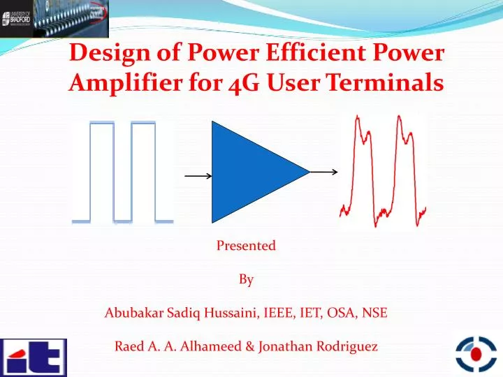
Design of Power Efficient Power Amplifier for 4G User Terminals. Presented By Abubakar Sadiq Hussaini, IEEE, IET, OSA, NSE Raed A. A. Alhameed & Jonathan Rodriguez. I suppose we need to ask where the power goes in mobile phones :

E N D
Design of Power Efficient Power Amplifier for 4G User Terminals Presented By Abubakar Sadiq Hussaini, IEEE, IET, OSA, NSE Raed A. A. Alhameed & Jonathan Rodriguez
I suppose we need to ask where the power goes in mobile phones: • Some is unavoidably used in communicating with the human being, so power has to be put into: • The audio signal and the visual information on the screen. • I don't think that the audio power could be reduced any more, unless the output amplifiers could be made more efficient, but I would imagine that they are all ready pretty good. • The power put into the screen might be reduced by using the headset display, and that could be a very significant argument for change in the way phones are used. 2
After that, we have power absorbed in the digital circuits, but the digital community is well on top of the issue of reducing that. • We have antenna and link budget issues: What determines the noise floor in the link? Is it the environment, or is it in the circuits? Using high gain antennas would reduce the transmitter power requirements • Then we have the power taken by the RF section: I would expect that the transmitter is far more of a problem than the receiver. • What kind of transmitter architecture do we use? Is it a basic linear system, and hence rather lossy • If you wanted to reduce the waste power in the transmitter, then you can learn lessons from the high-power broadcasting community who have used things like Doherty modulation and delta modulation 3
Outline • Motivation • Introduction • Power consumptions • Innovation • State of the art 4
Outline • Design • Operation • Results • Conclusion 5
Motivation • ICT power consumption • This is 3% of global power consumption • 2% of global CO2 emissions • Power consumption of ICT is increasing by 16-20% per year 7
Introduction • Highly integrated • Reconfigurable • Power Efficient • Low-Cost 8
Introduction • Multi-standard radios (GSM, UMTS,WCDMA, DVB-T, Mobile WiMAX) Thisradioscantheavailablespectrumandchangeitsnetwork parameters(frequency, bandwith, modulation) for maximum data transfer 9
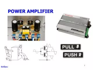
Power consumptions • Power amplifier consumes the highest power and convert more than 50% of the power into heat 10
Innovation • An efficient architecture and maintaining the QoS • Radio implementation: Power amplifier Antennas and antenna interface DSP • Radio functionality: Energy efficient modulation and coding Network coding and cooperative networks 11
State of the art 12 • Techniques such as Chireix outphasing, Doherty configuration, Kahn envelope elimination and Restorations(EER), And Envelope tracking (ET) • These will allow PAs to achieved good efficiency over a wide range of output power, yielding better overall efficiency
Design Propose block diagram of Doherty RF power amplifier 13
Operation PA 1 Z Z PA 2 Z Block diagram of Doherty power amplifier 14
Operation PA 1 Z X Z PA 2 Z Block diagram of Doherty power amplifier 15
Prototype 1 Implemented prototype of proposed Doherty RF power amplifier 16
Prototype 2 Power splitter 17
Result 1 Insertion loss 18
Result 2 Phase difference 19
Result 3 Gain Characteristics 20
Result 4 AM-AM Characteristics 21
Result 5 AM-PM Characteristics 22
Result 6 Power-Added Efficiency 23
Result - Comparison Comparison performance of Class B and Load modulation at Pout 1dB compression point 24
Conclusion The performance comparisons between Doherty RF power amplifier and conventional class B RF power amplifier are performed. The achieved results of the proposed design process have shown an excellent efficiency and power performances. Applying Doherty technique can significantly reduce the CO2 emission and power consumption in the transceiver. The self-managing characteristic of the Doherty RF power amplifier has made its implementation more attractive. 25
I Thank you! Please, any Question? E-mail: ash@av.it.pt Web: http://www.av.it.pt/4TELL/ 26