Download
1 / 33
330 likes | 787 Views
ECE 434 Advanced Digital System L12. Electrical and Computer Engineering University of Western Ontario. Example: Keypad Scanner. Preparation material Telephone keypad scanner Section 3.5 in the textbook Implemented using PLD (not relevant for you). Block Diagram.

E N D
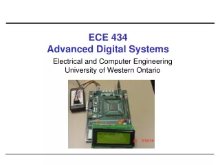
ECE 434Advanced Digital SystemL12 Electrical and Computer EngineeringUniversity of Western Ontario
Example: Keypad Scanner • Preparation material • Telephone keypad scanner • Section 3.5 in the textbook • Implemented using PLD (not relevant for you)
Block Diagram • Keypad is wired in matrix form • switches are at the intersections of rows and columns • Assumption: only one key is pressed at time • N=N3N2N1N0 • 0 – 0000 • ... • 9 – 1001 • * - 1010 • # - 1011 • V=1: when valid key is detected it is active for one clock cycle time
Scan Procedure • Apply logic 1s to columns C0, C1, C2 and wait • If any key is pressed a 1 will appear on R0, R1, R2, or R3 • Apply 1 to column C0 only; if any of Ri’s is 1, a valid key is detected;set V=1 and corresponding N • If no key is detected in column C0 apply 1 on C1;Repeat the same for C2 • When a valid key is detected, apply 1s to C0, C1, C2 and wait until no key is pressed • ensure that only one valid signal is generated each time a key is pressed
Debouncing • Problem: with mechanical switch the contact will bounce causing noise in the switch output • contact may bounce for several milliseconds • Solution: after a switch closure has been detected, wait for bounce to settle down before reading the key
Debouncing and Synchronization Circuit • Proposed debouncing circuit • Important:clock cycle time must be greater than the bounce time
Scanner Modules Scanner
Scanner • Problem: what is Kd in S5 if we have a key pressed in column C2? Solution
Review: Networks for Arithmetic Operations Case Study: Serial Parallel Multiplier Note: we use unsigned binary numbers
Block Diagram of a Binary Multiplier Ad – add signal // adder outputs are stored into the ACC Sh – shift signal // shift all 9 bits to right Ld – load signal // load multiplier into the 4 lower bits of the ACC and clear the upper 5 bits
Multiplier Control with Counter • Current design: control part generates the control signals (shift/add) and counts the number of steps • If the number of bits is large (e.g., 64),the control network can be divided intoa counter and a shift/add control
Multiplier Control with Counter (cont’d) Add-shifts control: tests St and M and generates the proper sequence of add and shift signals Counter control: counter generates a completion signal K that stops the multiplier after the proper number of shiftshave been completed
Multiplier Control with Counter (cont’d) • Increment counter each time a shift signal is generated • Generate K after n-1 shifts occured
Array Multiplier • What do we need to realize Array Multiplier? AND gates = ? FA = ? HA = ?
Array Multiplier (cont’d) • Complexity of the N-bit array multiplier • number of AND gates = ? • number of HA = ? • number of FA = ? • Delay • tg – longest AND gate delay • tad – longest possible delay through an adder
Multiplication of Signed Binary Numbers • How to multiply signed binary numbers? • Procedure • Complement the multiplier if negative • Complement the multiplicand if negative • Multiply two positive binary numbers • Complement the product if it should be negative • Simple but requires more hardware and timethan other available methods
Multiplication of Signed Binary Numbers • Four cases • Multiplicand is positive, multiplier is positive • Multiplicand is negative, multiplier is positive • Multiplicand is positive, multiplier is negative • Multiplier is negative, multiplicand is negative • Examples • 0111 x 0101 = ? • 1101 x 0101 = ? • 0101 x 1101 = ? • 1011 x 1101 = ? Preserve the sign of the partial product at each step If multiplier is negative, complement the multiplicand before adding it in at the last step
Faster Multiplier Move wires from the adder outputs one position to the right =>add and shift can occur at the same clock cycle
To Do • Read chapters 4.1, 4.2, 4.3, 4.4 • Tutorials • Design project 2: 16-bit ALU