Download

1 / 39
390 likes | 400 Views
ECE 434 Advanced Digital System L14. Electrical and Computer Engineering University of Western Ontario. Review: Faster Multiplier. Move wires from the adder outputs one position to the right => add and shift can occur at the same clock cycle. Review: State Graph for Faster Multiplier.

E N D
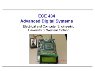
ECE 434Advanced Digital SystemL14 Electrical and Computer EngineeringUniversity of Western Ontario
Review: Faster Multiplier Move wires from the adder outputs one position to the right =>add and shift can occur at the same clock cycle
Digital design with SM Charts • State graphs used to describe state machines controlling a digital system • Alternative: use state machine flowchart
State Machine Charts • SM chart or ASM (Algorithmic State Machine) chart • Easier to understand the operation of digital system by examining of the SM chart instead of equivalent state graph • SM chart leads directly to hardware realization
SM Blocks SM chart is constructed from SM blocks State S1 is entered => Z1 and Z2 become 1 if X1=0 Z3 and Z4 become 1 if X1=1 and X3=0 Z5 become 1
Derivation of SM Charts • Binary Multiplier • Dice Game
Electronic Dice Game Block diagram 1. Two counters simulate the roll of dice (1-6); sum of two counters is in range of 2-12 2. Reset – initiate new game 3. Rb – roll button; when the roll button is pressed the counters count at high speed; when the button is released, the values of counters are displayed and game can proceed.
Electronic Dice Game - Description • First roll • player wins if the sum is 7 or 11 • player loses if the sum is 2, 3 or 12 • otherwise, the sum obtained in the first roll is referred as a point, and player must roll the dice again • Second roll (or subsequent roll) • player wins if the sum equals the point • player loses if the sum is 7 • otherwise, player rolls again until she/he finally wins or loses
Control Network for Dice Game • Input signals to the control network • D7 – 1 if the sum of the dice is 1 • D711 – (7 or 11) • D2312 – (2, 3, 12) • Eq – 1 if the sum equals the number stored in the point register • Rb – 1 when the roll button is pressed • Reset – 1 when the reset button is pressed • Output from the control network • Roll=1 – enables the dice counters • Sp=1 – sum is stored in the point register • Win=1 – turns on win light • Lose=1 – turns on lose light
To Do • Read chapters 5.1, 5.2
AppendixWriting Test Benches – Another Example library IEEE; use IEEE.std_logic_1164.all; use IEEE.std_logic_unsigned.all; entity SELECTOR is port( A: in std_logic_vector(15 downto 0); SEL: in std_logic_vector(3 downto 0); Y: out std_logic); end SELECTOR; • MUX 16 to 1 • 16 data inputs • 4 selection inputs architecture RTL of SELECTOR is begin Y <= A(conv_integer(SEL)); end RTL;
Appendix: Assert Statement • Checks to see if a certain condition is true,and if not causes an error message to be displayed • Four possible severity levels • NOTE • WARNING • ERROR • FAILURE • Action taken for a severity level depends on the simulator assert boolean-expression report string-expression severity severity-level;
AppendixWriting Test Benches – Another Example library IEEE; use IEEE.std_logic_1164.all; use IEEE.std_logic_arith.all; entity TBSELECTOR is end TBSELECTOR; architecture BEH of TBSELECTOR is component SELECTOR port( A: in std_logic_vector(15 downto 0); SEL: in std_logic_vector(3 downto 0); Y: out std_logic); end component; signal TA : std_logic_vector(15 downto 0); signal TSEL : std_logic_vector(3 downto 0); signal TY, Y : std_logic; constant PERIOD : time := 50 ns; constant STROBE : time := 45 ns;
AppendixWriting Test Benches – Another Example begin P0: process variable cnt : std_logic_vector(4 downto 0); begin for j in 0 to 31 loop cnt := conv_std_logic_vector(j, 5); TSEL <= cnt(3 downto 0); Y <= cnt(4); A <= (A’range => not cnt(4)); A(conv_integer(cnt(3 downto 0))) <= cnt(4); wait for PERIOD; end loop; wait; end process;
AppendixWriting Test Benches – Another Example begin check: process variable err_cnt : integer := 0; begin wait for STROBE; for j in 0 to 31 loop assert FALSE report “comparing” severity NOTE; if (Y /= TY) then assert FALSE report “not compared” severity WARNING; err_cnt := err_cnt + 1; end if; wait for PERIOD; end loop; assert (err_cnt = 0) report “test failed” severity ERROR; assert (err_cnt /= 0) report “test passed” severity NOTE; wait; end process; sel1: SELECTOR port map (A => TA, SEL = TSEL, Y => TY); end BEH;