Download
1 / 33
330 likes | 335 Views
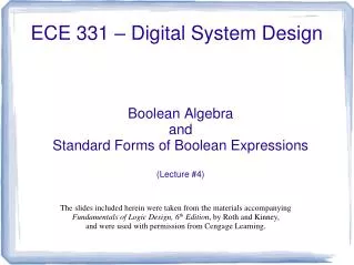
ECE 434 Advanced Digital System L03. Electrical and Computer Engineering University of Western Ontario. Outline. What we know Laws and Theorems of Boolean Algebra Simplification of Logic Expressions Using Laws and Theorems of Boolean Algebra or Using K-maps

E N D
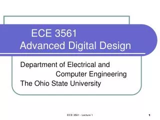
ECE 434Advanced Digital SystemL03 Electrical and Computer EngineeringUniversity of Western Ontario
Outline • What we know • Laws and Theorems of Boolean Algebra • Simplification of Logic Expressions • Using Laws and Theorems of Boolean Algebra or Using K-maps • Design Using only NAND or only NOR gates • Tri-state buffers • Basic Combinational Building Blocks • Multiplexers • Decoders • What we do not know • What are basic combinational building blocks • Multiplexers • Decoders • Encoders • How to implement functions using ROMs, PLAs, and PALs
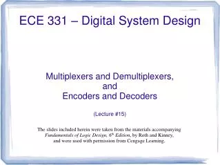
Review:Combinational-Circuit Building Blocks • Multiplexers • Decoders • Encoders • Code Converters • Comparators • Adders/Subtractors • Multipliers • Shifters
Multiplexers: 2-to-1 Multiplexer • Have number of data inputs, one or more select inputs, and one output • It passes the signal value on one of data inputs to the output w s 0 w 0 0 f s f w 1 1 w 1 (a) Graphical symbol (c) Sum-of-products circuit f s w 0 0 w 1 1 (b) Truth table
Review:Synthesis of Logic Functions Using Muxes w w w f 1 2 3 w w f 1 2 0 0 0 0 0 0 0 0 0 1 0 w 0 1 3 0 1 0 0 w 1 0 3 w 0 1 1 1 2 1 1 1 w 1 1 0 0 0 0 1 0 1 1 w 3 1 1 0 1 f 1 1 1 1 1 (a) Modified truth table (b) Circuit
Review:Decoders: n-to-2n Decoder • Decode encoded information: n inputs, 2n outputs • If En = 1, only one output is asserted at a time • One-hot encoded output • m-bit binary code where exactly one bit is set to 1 w y 0 0 n n 2 inputs w outputs n – 1 y n Enable 2 – 1 En
Decoders: 2-to-4 Decoder w w y y y y En 1 0 0 1 2 3 w 0 0 0 0 1 0 0 1 y 0 0 1 0 1 0 0 1 w 1 1 1 0 0 0 1 0 1 1 1 0 0 0 1 y x x 0 0 0 0 0 1 (a) Truth table y 2 w y 0 0 w y y 1 1 3 y 2 En y En 3 (c) Logic circuit (b) Graphic symbol
Encoders • Opposite of decoders • Encode given information into a more compact form • Binary encoders • 2n inputs into n-bit code • Exactly one of the input signals should have a value of 1,and outputs present the binary number that identifies which input is equal to 1 • Use: reduce the number of bits (transmitting and storing information) w 0 y 0 n n 2 outputs inputs y n – 1 w n 2 – 1
Encoders: 4-to-2 Encoder w w w w y y 3 2 1 0 1 0 w 0 0 0 0 1 0 0 w 1 y 0 0 1 0 0 1 0 0 1 0 0 1 0 w 2 1 0 0 1 1 0 y 1 w 3 (a) Truth table (b) Circuit
Encoders: Priority Encoders • Each input has a priority level associated with it • The encoder outputs indicate the active inputthat has the highest priority (a) Truth table for a 4-to-2 priority encoder w w w w y y z 3 2 1 0 1 0 0 0 0 0 d d 0 0 0 0 1 0 0 1 x 0 0 1 0 1 1 x x 0 1 1 0 1 x x x 1 1 1 1
Code Converters • Convert from one type of input encoding to a different output encoding • E. g., BCD-to-7-segment decoder c e g w w w w a b d f 3 2 1 0 a a 0 0 0 0 1 1 1 1 1 1 0 b w 0 0 0 1 0 1 1 0 0 0 0 0 f b c w 0 0 1 0 1 1 0 1 1 0 1 1 d w 0 0 1 1 1 1 1 1 0 0 1 g 2 e e c w 0 1 0 0 0 1 1 0 0 1 1 3 f 0 1 0 1 1 0 1 1 0 1 1 g d 0 1 1 0 1 0 1 1 1 1 1 (b) 7-segment display 1 1 1 0 1 1 1 0 0 0 0 (a) Code converter 1 1 1 1 1 1 1 1 0 0 0 1 0 0 1 1 1 1 1 0 1 1 (c) Truth table
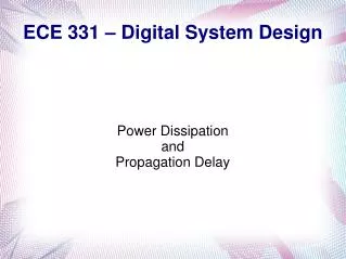
Hazards in Combinational Networks • What are hazards in CM? • Unwanted switching transients at the output (glitches) • Example • ABC = 111, B changes to 0 • Assume each gate has propagation delay of 10ns
Hazards in Combinational Networks • Occur when different paths from input to output have different propagation delays • Static 1-hazard • a network output momentarily go to the 0 when it should remain a constant 1 • Static 0-hazard • a network output momentarily go to the 1 when it should remain a constant 0 • Dynamic hazard • if an output change three or more times, when the output is supposed to change from 0 to 1 (1 to 0)
AB 01 10 00 11 C 1 1 1 1 1 1 1 0 1 Hazards in Combinational Circuits AB 01 10 00 11 C 1 0 1 To avoid hazards: every par of adjacent 1s should be covered by a 1-term
Hazards in Combinational Circuits Why do we care about hazards? • Combinational networks • don’t care – the network will function correctly • Synchronous sequential networks • don’t care - the input signals must be stable within setup and hold time of flip-flops • Asynchronous sequential networks • hazards can cause the network to enter an incorrect state • circuitry that generates the next-state variables must be hazard-free • Power consumption is proportional to the number of transitions
Programmable Logic Devices • Read Only Memories (ROMs) • Programmable Logic Arrays (PLAs) • Programmable Array Logic Devices (PALs)
Read-Only Memories • Store binary data • data can be read out whenever desired • cannot be changed under normal operating conditions • n input lines, m output lines => array of 2n m-bit words • Input lines serve as an address to select one of 2n words • Use ROM to implement logic functions? • n variables, m functions
ROM Types • Mask-programmable ROM • Data is permanently stored (include or omit the switching elements) • Economically feasible for a large quantity • EPROM (Erasable Programmable ROM) • Use special charge-storage mechanism to enable or disable the switching elements in the memory array • PROM programmer is used to provide appropriate voltage pulses to store electronic charges • Data is permanent until erased using an ultraviolet light • EEPROM – Electrically Erasable PROM • erasure is accomplished using electrical pulses (can be reprogrammed typically 100 to 1000 times) • Flash memories - similar to EEPROM except they use a different charge-storage mechanism • usually have built-in programming and erase capability, so the data can be written to the flash memory while it is in place, without the need for a separate programmer
Programmable Logic Arrays (PLAs) • Perform the same function as a ROM • n inputs and m outputs – m functions of n variables • AND array – realizes product terms of the input variables • OR array – ORs together the product terms
Modified Truth Table for PLA • 0 – variable is complemented • 1 – variable is not complemented • - – not present in the term
Using PLA: An Example Eight different product terms are required!? For PLA we want to minimize the total number of product terms, not the number of product terms for each function separately!
1 1 1 1 1 1 1 1 1 1 1 1 1 1 1 1 1 1 1 1 1 1 1 1 Using PLA: An Example ab ab ab 01 10 00 11 01 10 00 11 01 10 00 11 cd cd cd 1 00 1 00 00 01 01 01 11 11 11 10 10 10 F1 F2 F3
Programmable Array Logic (PALs) • PAL is a special case of PLA • AND array is programmable and OR array is fixed • PAL is • less expensive • easier to program
Programmable Array Logic (PALs) Unprogrammed Programmed
PALs • Typical PALs have • from 10 to 20 inputs • from 2 to 10 outputs • from 2 to 8 AND gates driving each OR gate • often include D flip-flops
To Do • Read • Textbook chapters 1.5, 3.1, 3.2, 3.3