Download
1 / 24
260 likes | 555 Views
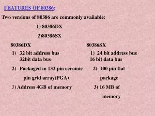
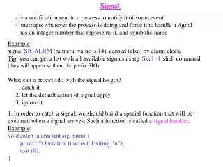
Signal Interface of 80386DX. Signal Interface. Signal Interface. Signals are arranged by functional groups. The # symbol indicates active low signal. When no # is present, the signal is active high. Example: M/IO# - High voltage indicates memory selected

E N D
Signal Interface • Signals are arranged by functional groups. • The # symbol indicates active low signal. • When no # is present, the signal is active high. • Example: M/IO# - High voltage indicates memory selected • - Low voltage indicates I/O selected
Signal Interface • Clock (CLK2): • It is divided by two internally to generate the internal processor clock. • The phase of internal processor clock can be synchronized to a known phase. • Data Bus (D0 through D31): • It has three-state bidirectional signals. • It can transfer data on 32- and 16-bit buses using a data bus sizing feature.
Signal Interface • Address Bus (A2 through A31) • These three-state outputs provide memory or I/O port addresses. • It can access 4GB of physical memory from 00000000H to FFFFFFFFH • Of the total 32-bits, only higher 30 are released by MP • A1 & A0 are used internally by MP to produce 4 bank enable signals(BE3# - BE0#)
Signal Interface • Byte Enable Outputs( BE0# -- BE3#) • enable 4 memory banks • indicates which bytes of the 32-bit data bus are involved with the current transfer. • BE0# applies to D0-D7 • BE1# applies to D8-D15 • BE2# applies to D16-D23 • BE3# applies to D24-D31 • No. of Byte Enables asserted indicates physical size of operand being transferred (1, 2, 3, or 4 bytes).
Signal Interface • Bus Cycle Definition Signals (W/R#, D/C#, M/IO# , LOCK#) • three-state outputs • W/R# :distinguishes b/w write and read cycles. • D/C# :distinguishes b/w data and control cycles. • M/IO# :distinguishes b/w memory and I/O cycles. • LOCK# :distinguishes b/w locked and unlocked bus cycles. It enables CPU to prevent other bus masters (like coprocessor) from gaining the control of system bus.
Signal Interface • Bus Cycle Definition Signals: These control signals are decoded by the bus control logic to decide which bus cycle to be performed
Signal Interface • Bus Control Signals(ADS#,READY#,NA#,BS16#): • indicates when a bus cycle has begun and allow other system hardware to control address pipelining, data bus width and bus cycle termination. • ADDRESS STATUS (ADS#) : indicates that a valid address is driven at 80386DX pins. • TRANSFER ACKNOWLEDGE (READY#) : indicates that the previous bus cycle is complete and bus is ready for next bus cycle. It is useful for interfacing slow peripherals
Signal Interface • NEXT ADDRESS REQUEST (NA#) : • This is used to enable address pipelining. • It indicates that the system is prepared to accept the next address even if the end of current cycle is not being acknowledged on READY#. • BUS SIZE 16 (BS16#) : • Asserting this input constrains current bus cycle to use only D0-D15 of data bus.
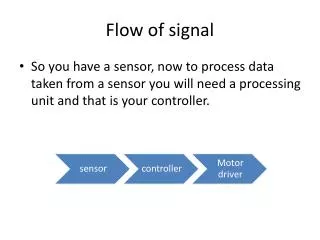
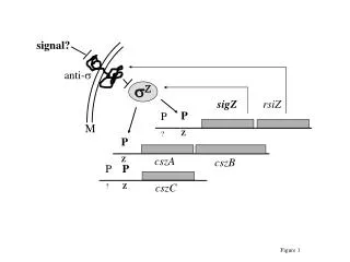
HOLD Bus Arbitration Signals (HOLD, HLDA) HLDA 80386 DMA Controller
Bus Arbitration Signals (HOLD, HLDA) • BUS HOLD REQUEST (HOLD): • This input indicates some other device requires bus mastership. • HOLD must remain asserted as long as any other device is a local bus master. • HOLD is not recognized while RESET is asserted. (i.e. RESET has priority over HOLD and places the bus into an idle state rather than hold acknowledge state) • HOLD is level-sensitive.
Bus Arbitration Signals (HOLD, HLDA) • BUS HOLD ACKNOWLEDGE (HLDA): • This output indicates 80386 has relinquished control of its local bus in response to HOLD asserted and it is in Bus Hold Acknowledge state. • This state offers near-complete signal isolation ( It is the only signal being driven by 80386) • The other output signals (D0-D31, BE0#-BE3#, A2-A31, W/R#, D/C#,M/IO#, LOCK# and ADS#) are in a high-impedance state so the requesting bus master may control them.
Coprocessor Interfacing • Intel 387DX numeric coprocessor is I/O mapped. • As Intel386DX begins supporting a coprocessor instruction, it tests the BUSY# and ERROR# signals to determine if the coprocessor can accept its next instruction • Intel 387DX can be given its command opcode immediately
Coprocessor Interface Signals (PEREQ, BUSY#, ERROR#) • COPROCESSOR REQUEST (PEREQ) : • This input signal indicates a coprocessor request for a data operand to be transferred to/from memory by Intel386 DX. • In response, Intel 386DX transfers information between the coprocessor and memory • Since Intel386 DX has internally stored the coprocessor opcode being executed, it performs the requested data transfer with the correct direction and memory address. • PEREQ is level-sensitive
Coprocessor Interface Signals (PEREQ, BUSY#, ERROR#) • COPROCESSOR BUSY (BUSY#) : • This input indicates that coprocessor is still executing an instruction and is not yet able to accept another. • This sampling of BUSY# input prevents overrunning the execution of a previous coprocessor instruction. • BUSY# is level-sensitive
Coprocessor Interface Signals (PEREQ, BUSY#, ERROR#) • COPROCESSOR ERROR (ERROR#) : • This input signal indicates that the previous coprocessor instruction generated a coprocessor error of a type not masked by coprocessor's control register. • This input is automatically sampled by Intel386 DX when a coprocessor instruction is encountered, and if asserted it generates exception 16 to access the error-handling software. • ERROR# is level-sensitive
Interrupt Signals (INTR, NMI, RESET) • MASKABLE INTERRUPT REQUEST (INTR): • This input indicates a request for interrupt service, which can be masked by Flag Register IF bit. • When processor responds to INTR input, it performs two interrupt acknowledge cycles and at the end of second, it latches an 8-bit interrupt vector on D0-D7 to identify source of interrupt. • INTR is level-sensitive • To assure recognition of an INTR request, INTR should remain asserted until the first interrupt acknowledge bus cycle begins.
Interrupt Signals (INTR, NMI, RESET) • NON-MASKABLE INTERRUPT REQUEST(NMI): • This input indicates a request for interrupt service which cannot be masked by software. • Because of fixed NMI slot, no interrupt acknowledge cycles are performed when processing NMI. • NMI is rising edge-sensitive • Once NMI processing has begun, no additional NMIs are processed until the next IRET instruction, which is typically the end of the NMI service routine.
Interrupt Signals (INTR, NMI, RESET) • RESET (RESET) : • This input signal suspends any operation in progress and places the Intel386 DX in a known reset state. • The Intel386 DX is reset by asserting RESET for 15 or more CLK2 periods • When RESET is asserted, all other input pins are ignored, and all other bus pins are driven to an idle bus state. • If RESET and HOLD are both asserted at a point in time, RESET takes priority. • RESET is level-sensitive
Signal Interfaces Table 5-3. Idle Bus State During Reset
Signal Interfaces • Vcc: These are system power supply lines • GND: These are return lines for the power supply