Download
1 / 35
570 likes | 1.19k Views
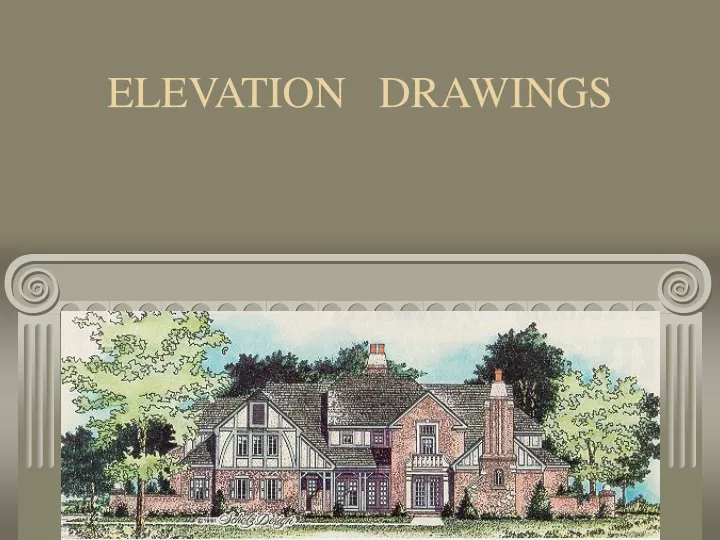
ELEVATION DRAWINGS. Introduction. An essential part of the design and drafting process Elevations are orthographic drawings showing outside/exterior views of the building Typically four(4) elevations are drafted

E N D
Introduction • An essential part of the design and drafting process • Elevations are orthographic drawings showing outside/exterior views of the building • Typically four(4) elevations are drafted • Information provided may include: roofing material, roof overhangs/slopes, siding or other exterior materials, chimney heights and materials, grading data, and footing depths
Introduction • Drawing scales for elevations • Match the scale of the floor plans, usually 1/4” = 1’-0” • Some larger buildings require smaller scales such as 1/8” or 1/16”
Types of Elevations 1. Presentations elevations are highly detailed drawings, more towards the artist type of drawings
Types of Elevations 2. Working drawing elevations are less artist but accurate and complete withall information necessary to build structure
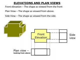
Elevation Views • Each 90 degree projection are called orthographic views • Typical four view are created • Front • Right side • Rear • Left side
Reason for Drafting Elevations • To show a picture view of the outside of the building, gives architect, owner, and contractor first hand information of building appearance before construction • To give vertical dimensions sufficient to help contractor in the construction • To show building materials in elevation and give callout information about each material
What Is Needed to Draft the Elevation • Knowledge of exterior construction materials and symbols representing these materials • Typical wall section and related sections showing vertical relationships, dimension, roof slope, same scale as the floor plan • Floor plans showing location of building features, such as doors, windows, building jogs, etc
Elevation Symbols • Symbols are different than section or plan symbols (see handout)
Building Material Symbols & Callout Examples • Callouts: • Vertical siding • 4x4 wood post • Brick • Slope • Finished floor • Door symbol
Building Material Symbols & Callout Examples • Callouts: • Glass • Redwood shingles • Stone
Wall Section • Simply drafted to the same scale as the floor plan ¼” = 1’-0”, showing all major elements, such as: • Footing depth • Grade level • Finished floor or sub-floor points • Floor thickness • Plate height • Roof overhangs • Chimney heights • Roof intersections
Complete picture of elevation How to Draw the Elevation Picture Drafting relationship between floor plan, section and elevation
Drafting Procedures Project elevation view from the floor plan to locate the sides of building window/door locations roof overhang location of chimney ridge of roof Project elevation view from the section to locate footing / foundation heights floor/ceiling heights fascia/roof heights
Vertical Dimensions • Vertical dimensions can be placed on an elevation using several methods: • 1) data reference points using key construction points as reference • 2) finish surface to finish surface--vertical dimension lines dimensioning from finish surface to finish surface • 3) key construction points--vertical dimension lines dimensioning from construction surfaces
1) Data Reference Points DATA REF
Drawing Technique • Floor plans technique • Cutting-plane and/or profile technique of floor plan • Elevation line techniques • 1) silhouette technique ***** • 2) shadow technique • 3) distance technique • 4) major-feature technique
Elevation Technique (1) • Silhouette technique • Oldest of techniques • Outline shown with thick line • Grade line thick only outside plan • Very easy method • Less realistic
Elevation Technique (2) • Shadow technique • One of the most difficult methods • Lines or edges away from the light source are thick lines • Light assumed to be coming from the upper left hand corner • Grade line is thick
Elevation Technique (3) • Distance technique • Method to show depth in the elevation • Near or close features/lines are thick • Far or distance lines are drawn thin • All accent lines black
Elevation Technique (4) • Major feature technique • Major drawing elements are emphasized with thick lines • Drawing elements of lesser importance are drafted with thin lines • Grade line is thick
Project Porch/house Section (Handout) Arrows from section locate vertical points or (heights) in the elevation This section is not usually drawn with such detail and is only used to help draft the elevation
Project Wall Section • Dimensions taken from wall section. Draft/place on left side of front elevation • Also dimensions needed on garage side---from top of foundation to top plate