Download
1 / 19
200 likes | 293 Views
Developing a SDR Testbed. Alex Dolan Mohammad Khan Ahmet Unsal Project Advisor Dr. Aditya Ramamoorthy. Presentation Overview. Background Information Project Overview System Design Progress and Plan. Background Information. Software Defined Radio USRP-2 DaughterBoard.

E N D
Developing a SDR Testbed Alex Dolan Mohammad Khan Ahmet Unsal Project Advisor Dr. Aditya Ramamoorthy
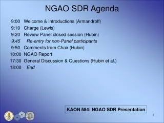
Presentation Overview • Background Information • Project Overview • System Design • Progress and Plan
Background Information • Software Defined Radio • USRP-2 • DaughterBoard
Project Overview Project Goal • Develop a Software Defined Radio network testbed, using MATLAB Simulink and USRP-2 • Evaluate MATLAB Simulink’s Versatility as a SDR platform
Requirements • Implement a SDR Testbed • Use of Universal Software Radio Peripheral-2 (USRP-2) • Use of MATLAB Simulink • Implement digital modulation schemes like FSK, BPSK, DBPSK, QAM • Implement simplified 802.11 MAC
Constraints • USRP-2 • Number of nodes • Frequency Range • Bandwidth • Transmission Power • Processing • CPU Cycles • Time
Assumptions • Tested under reasonable conditions • Normal level of noise • Controlled transmission range
Resources • 2 USRP-2s • Sample rate of 100 MHz • 2 Dell Optiplex 980 Computers • Intel Core i7 Processor • Daughterboards • Various daughterboards for different frequency bands • Able to transmit and receive up to 5 GHz
Design Physical Layer • Design MAC Layer • Testing and Logging Design Process
System Decomposition • Physical layer: • USRP-2 • Simulink – DSP and digital communications • MAC: • Coordinates transmission among nodes. • Testing and Logging: • The tools used to test the system. • Tracks progress and success.
Physical Layer • Simulink signal processing • FSK, PSK, QAM modulation/demodulation • Synchronization and packetization • Error control • USRP-2 hardware • Ethernet interface with 100 MSamples/s A/D conversion
MAC Layer • Coordinate channel access between nodes • Simplified 802.11 implementation • Carrier sense multiple access with collision avoidance (CSMA/CA) • Written in C++ or embedded MATLAB.
MAC • Design a MAC that allows simultaneous transmissions when both interfered messages can be decoded • Distributed Algorithm • Similar to 802.11 distributed coordinate function • Use RTS and CTS messages to coordinate interfering transmissions
Testing and Logging • Select logging/testing options • Logging data to file from individual layers/components • Scopes/Visualization of data from individual layers/components • Generation of statistics • Validation
Design Physical Layer in Simulink. • Design each component in Simulink. • Test in controlled MATLAB environment. • Test using USRP-2 and Simulink. • Introduce MAC layer • Move from point to point and introduce more nodes. • Compare results to simulations and expected results. • Observe BER, data rates, etc. Testing Procedure