Download
1 / 12
120 likes | 192 Views
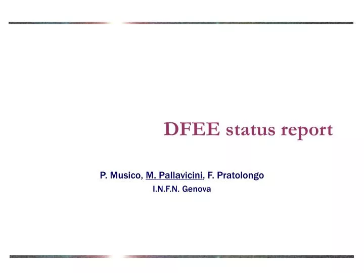
DFEE status report. P. Musico, M. Pallavicini , F. Pratolongo I.N.F.N. Genova. Contents. Activities since Palermo meeting Test DFEE prototype Continue developing IEFE, Interface to Euso Front End. DFEE protoype on test board. Magnified. Open chip in its case.

E N D
DFEE status report P. Musico, M. Pallavicini, F. Pratolongo I.N.F.N. Genova
Contents • Activities since Palermo meeting • Test DFEE prototype • Continue developing IEFE, Interface to Euso Front End
Magnified Open chip in its case
Analog test output (1 channel) 100 ns wide pulse 10 ns wide pulse
DFEE prototype tests (I) Threshold scan with Input pulse corresponding to ½ photoelectron
DFEE prototype tests (II) Threshold scan with Input pulse corresponding to 1 photoelectron
Gain uniformity : 16 channels Gain uniformity derived from threshold scan 2 pe 1 pe ½ pe
Power needs measurements Total power with no clock: 9.9 mW 0.6 mW/channel • We have carefully measured power needs • Chip uses 3 power lines, 3.3 V each : VADD, VCDD, VDD Measured currents (no digital clock): IADD =1.1 mAICDD=1.4 mAIDD=0.5 mA With continuous clock, of course things get worse: Next chip generations will probably not use continuos clock
Future activity • Continue tests • Test digital functions (long job) • Interface DFEE to existing microcell • Build the first section of Euso focal surface! • Build IEFE and connect microcell to PC • Future design efforts • Start integration with AFEE • Implement possible new triggers • Groups of channels for triggering • Pattern recognition ? Need power, too early to say how much.Need also a big effort with TEO
IEFE • In order to test all chip functions, a dedicated interface is needed. • Main features: • USB interface and 19 V laptop power supply (easy to use anywhere with a laptop) • Up to 8 chip handled in parallel. • Hardware interface (START, STOP and such) for fast timing sequences • Windows (and maybe Linux) based software interface • Block diagram designed. An engineer from Torino and one from Genova is working on the • Most of the functions will be handled by fully programmable devices • Remote re-programming via USB for multi-purpose use • Some logic analyzer functionalities included to handle macrocell logic signals, if needed. • It may become the standard testing tool for a microcell