Download

1 / 22
420 likes | 895 Views
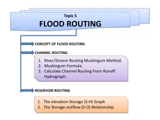
Flood Routing Applied Hydrology. Flow Routing. Channel Routing Reservoir Routing. Routing. Routing is the process of predicting temporal and spatial variation of a flood wave as it travels through a river (or channel reach or reservoir. Two types of routing can be performed:

E N D
Flow Routing • Channel Routing • Reservoir Routing
Routing Routing is the process of predicting temporal and spatial variation of a flood wave as it travels through a river (or channel reach or reservoir. • Two types of routing can be performed: • Hydrologic Routing • Hydraulic Routing
Hydrologic Routing In hydrologic routing techniques, the equation of continuity and some linear or curvilinear relation between storage and discharge within the river or reservoir is used. • Applications of routing techniques: • Flood predictions • Evaluation of flood control measures • Assessment of effects of urbanization • Flood warning • Spillway design for dams
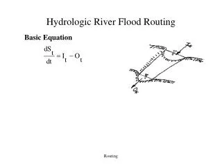
Hydrologic Routing Continuity Equation: Where I = Inflow O= Outflow DS/Dt = Rate of change of storage Problem: You have a hydrograph at one location (I) You have river characteristics (S=f(I,O)) Need: A hydrograph at different location (O)
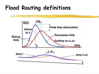
Hydrologic Routing Hydrograph at point A Hydrograph at point B • The hydrograph at B is attenuated due to storage characteristics of the stream reach. • Assumption: no seepage, leakage, evaporation, or inflow from the sides.
Hydrologic Channel Routing Muskingum Method: Flow in a channel wedge prism wedge prism prism Storage in wedge: KX(I-O) Storage in prism: KO So, Storage S=KX(I-O)+KO
Muskingum Method Storage S=KO+KX(I-O) rewritten as S=K[XI+(1-X)O] Where S = Storage in the river reach K = Storage time constant (T) X = A weighting factor that varies between 0 and 0.5 (defines relative importance of inflow and outflow on storage) If X=0.5 pure translation, if X=0 max attenuation
Muskingum Method How it works: Write continuity equation as Where I = Average inflow during Dt O= Average outflow during Dt or
Muskingum Method Combine and rearrange Simplified into the routing equation: Subscript 1 refers to t1and 2 to t2 = (t+Dt)
Muskingum Method Need K and Dt in the same units
Estimation of K, X and Dt K=0.6L/vavg Where L = Length of river reach Vavg = Average velocity in reach Constraint K<tp/5 (divide reach up if needed) X = 0.2 for most cases X = 0.4 for steep channels with narrow flood plains X = 0.1 for mild channels with broad flood plains 2KX<Dt<2K(1-X) and ideally Dt<tp/5. Choose Dt in numbers that divide into 24 (Daily data)
Example 1 Tp = 4 hr, L = 2 mi, vavg = 2.5 ft/s, wide flat floodplain Solution: K = 0.6L/vavg = 0.6(2x5280)/2.5=2,534 sec = 0.7 hr X = 0.1 Dt: 2KX = 2(0.7)0.1 = 0.14 2K(1-X) = 2(0.7)0.9 = 1.26 0.14<Dt<1.26 and Dt<tp/5 or Dt<0.8 hr, so Dt = 0.5 hr is most accurate.
Example 2 Channel Routing in spreadsheet
Reservoir Routing • Storage-Indication Method: • Apply the storage-indication method for reservoirs that have a spillway. • Assume that storage (S)=0 when no overflow occurs (surcharge storage). • Apply this to an ungated spillway like a weir, outlet discharge pipe, or gated spillway with fixed position.
Reservoir Routing • Use a relationship between outflow (O) and elevation head (H). For example, for a broad crested weir: • Q=CLH3/2 • Where • O = Discharge at the outlet (cfs) • C = Discharge coefficient of weir (cfs) • L = Length of crest (ft) • H = Depth above spillway (ft)
Reservoir Routing • Two relationships specific for reservoir: • Storage-Head Relationship • Outflow-Head Relationship • Need: • An inflow hydrograph • A starting elevation above spillway
Reservoir Routing Use the continuity equation as: Where I = Average inflow during Dt O = Average outflow during Dt Or Where subscripts denote the time interval
Reservoir Routing For i=1, we know Ii and Ii+1 (Initially) and Si (Initially) We do not know Oi+1 and Si+1 So, we rewrite “Knowns = Unknowns”
Reservoir Routing We can find Oi+1, if we have a relationship between term on RHS and O. This is possible using the so-called Storage-Indication Curve.
Routing Steps • Set i=1, obtain initial head and inflow hydrograph. • Find initial outflow O1 corresponding to initial head above spillway. • Find 2S/Dt for S(H) relationship. • From the continuity equation, calculate • Enter storage-indication curve to find O2. • Calculate • Change i=2 • From continuity equation, calculate • Repeat steps 4-7, and so on…..
Example 3 Reservoir Routing in spreadsheet