Download
1 / 36
500 likes | 867 Views
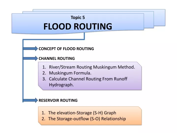
Topic 5 FLOOD ROUTING. CONCEPT OF FLOOD ROUTING. CHANNEL ROUTING. River/Stream Routing Muskingum Method. Muskingum Formula. Calculate Channel Routing From Runoff Hydrograph. RESERVOIR ROUTING. The elevation-Storage (S-H) Graph The Storage-outflow (S-O) Relationship. FLOOD ROUTING.

E N D
Topic 5 FLOOD ROUTING CONCEPT OF FLOOD ROUTING CHANNEL ROUTING River/Stream Routing Muskingum Method. Muskingum Formula. Calculate Channel Routing From Runoff Hydrograph. RESERVOIR ROUTING The elevation-Storage (S-H) Graph The Storage-outflow (S-O) Relationship
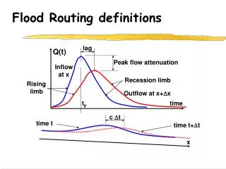
CONCEPT OF FLOOD ROUTING Flood routing is a process used to predict the temporal and spatial variations of a flood hydrograph as it moves through a river reach or reservoir Flood routing is used to predict the magnitudes, volumes, and temporal patterns of a flood hydrograph as it translates down a river reach or reservoir The effects of storage and flow resistance within a river reach are reflected by changes in hydrograph shape and timing as the floodwave moves from upstream to downstream In general, routing methods are classified as hydrologic and hydraulic, depending, respectively, on whether the methods are based on empirical or physical process equations of motion
Applications (Types of flood routing) • Reservoir Routing • Channel Routing
Flood Routing Hydrologic Routing Hydraulic Routing (Based on Continuity Equation) Based on Momentum equation Reservoir Routing Channel Routing
River/ Channel vs. Reservoir Routing River routing differs from reservoir routing in that storage in a river reach of length L depends on more than just outflow The peak of the outflow hydrograph from a reach is usually attenuated and delayed compared with that inflow hydrograph River vs. Reservoir Routing Because storage in a river reach is a function of whether stages rising or falling, storage in this case is a function of both outflow and inflow for the routing reach Reservoir routing is generally easier to perform than river routing because storage-discharge relations for pipes, weirs, and spillways are single-valued functions independent of inflow
Muskingum Equation • One of the most popular channel routing • Uses the hydrologic spatially lumped form of the continuity equation • First applied to Muskingum river in Ohio state, USA • Tributary of Ohio river • Length 179 km(111 mi ) • Basin area 20,852 km²(8,051 mi² )
Muskingum Method The Muskingum method was developed by McCarthy (1938) and utilizes the continuity equation and a storage relationship that depends on both inflow and outflow In natural channels the exact relationship between inflow, outflow, and storage is usually quite complicated, but Muskingum channel routing procedure makes use of the simplifying assumption that the relationship can be approximated as: S = K[xI + (1-x)O], where K is a constant, whose units are those of time and the value of K approximates the travel time of the flood wave through the reach x is a factor that weighs the relative influences of inflow and outflow upon the storage. For most river channels, x lies between 0.1 and 0.3, indicating both attenuation and translation. The modal value is about 0.2
Muskingum Equation (Contd…) • Using m =1.0, equation 9. reduces to a linear relationship for S in terms of I and Q as • x – weighting factor varies bet. 0 to 0.5 • When x = 0, storage function is discharge only • Linear storage or linear reservoir • x = 0.5 both inflow and outflow are equally imp. In determining storage • K – storage-time constant ~ time of travel of a flood wave through the channel reach …..10 …..11
Estimation of K and x • Like reservoir routing in channel routing also we can draw inflow-outflow hydrograph through a channel reach • The increment in storage at any time t due to a small time period t can be calculated. • The summation of the various incremental storage gives us the channel storage Vs time relationship
Estimation of K and x (contd…) • Once this storage Vs time is known for a reach • Assume a value of x and estimate for various time intervals • Draw the graph between the storage and if the assumed x is correct we will get a linear line, else a loop will be formed • By trial and error find the value of x until a straight line is formed • Inverse slope of the line will give the value of K Let us see how to estimate this using an example
The following inflow and outflow hydrographs were observed in a river reach. Estimate the values of Kand x applicable to this reach for use in the Muskingum equation.
Calculate Channel Routing From Runoff Hydrograph Example: Route the inflow hydrograph tabulated in the following table through a river reach for which x = 0.20 and K = 8 hours . Assume that inflow equals outflow for the first day.
The Reservoir Storage Concept • At time t1, inflow and outflow are equal and the maximum storage is reached • For times exceeding t1, outflow exceeds inflow and the reservoir empties • Area C represents the volume of water that flows out of the reservoir and must equal area A if the reservoir begins The Reservoir Storage Concept and ends at the same level • The peak of the outflow from reservoir should intersect the inflow hydrograph, since, in general, outflow is uniquely determined by reservoir storage or level • Storage routing through a reservoir will generally attenuate the peak outflow and lag the time to peak for the outflow hydrograph
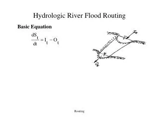
The Reservoir Storage Concept • The rate of change of storage can be written as the continuity equation I – O = Where I = inflow O = outflow ΔS = change in storage Δt = change in time
Reservoir Routing • To predict the variations of reservoir elevation and outflow discharge with time • Study the effect of a flood wave entering a reservoir • Volume-elevation characteristic of reservoir • Outflow-elevation relationship for the spillways and other outlets • Reservoir Routing is Essential • Design of the capacity of spillway/other reservoir outlets • Location and sizing of the capacity of reservoirs to meet specific requirements
Hydrologic Storage Routing(Level Pool Routing) horizontal water surface is assumed in the reservoir • Uncontrolled spillway provided …..6
Data required for reservoir routing • Storage volume vs elevation for the reservoir • Water-surface elevation vs outflow and hence storage vs outflow discharge • Inflow hydrograph, I = I (t) • Initial values of S, I and Q at time t = 0
Methods for Flood Routing Through a Reservoir • Modified Pul’s Method • Goodrich Method • Standard Fourth – Order Runge-Kutta Method (SRK)
Goodrich MethodSemi-graphical Method • On rearranging equation 3 • On collecting known and initial values • In the above equation the starting inflow and end inflow at time period t is known (read it from the inflow hydrograph), and the initial storage and discharge is also known • Then estimate the value remember both are unknown quantities …..7 …..8
Contd…. • To know the discharge, we need a graph between elevation Vs • Thus called as semi graphical method • This quantity is called storage-elevation-discharge data • The graph gives the relationship between discharge and elevation • From graph estimate the elevation • From elevation estimate the discharge • Is flood routing is too confusing • The following problem will help to understand this method
Route the following flood hydrograph through the reservoir by Goodrich method: Inflow hydrograph The storage-elevation-discharge data is as follows: The initial conditions are when t = 0, the reservoir elevation is 100.60 m.
Step 1: Construct the storage-elevation-discharge curve • Assume a time period of 6 hr (t ) • Equal to time of discharge measurement in the inflow hydrograph • Estimate the values of • Plot a graph • elevation-Vs-discharge • Elevation-Vs- • For initial time period t=0 find the Q2 and From the graph
Lag Attenuation What we achieved through this flood routing • The peak discharge magnitude is reduced, this is called attenuation. • 2. The peak of outflow gets shifted and is called as lag • 3. The difference in rising limb shows the reservoir is storing the water • 4. The difference in receding limb shows the reservoir is depleted. • 5. When the outflow is through uncontrolled spillway, the peak of outflow always occurs at point of inflection of inflow hydrograph and also is the point at which the inflow and outflow hydrograph intersect. Reservoir storing Reservoir Depleting