Download
1 / 13
130 likes | 231 Views
Mapping E/R Diagrams to Relational Database Schemas. Second Half of Chapter 3. E/R Relation Model (Example). since. since. name. name. dname. dname. ssn. did. did. budget. budget. lot. (0,*). (1,1). Departments. Employees. Manages. (0,*). hours_worked. (0,*). Works_In. .

E N D
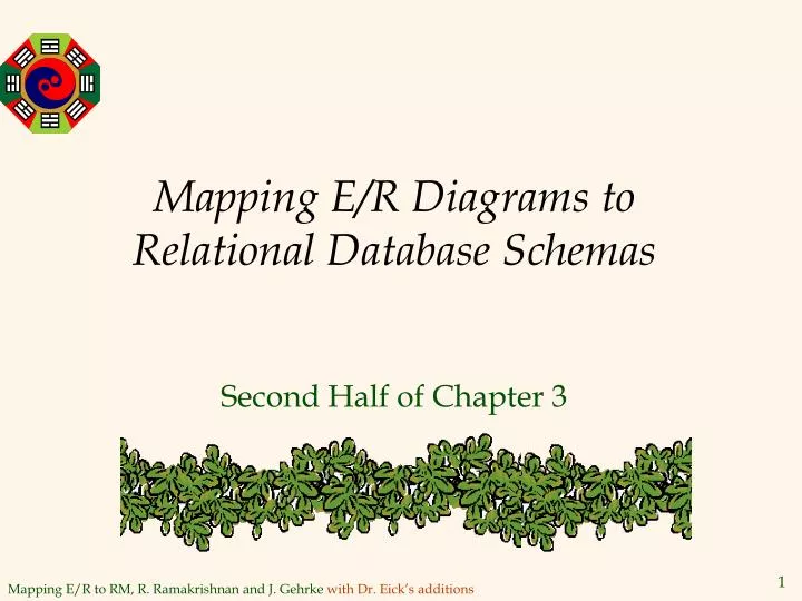
Mapping E/R Diagrams toRelational Database Schemas Second Half of Chapter 3
E/R Relation Model (Example) since since name name dname dname ssn did did budget budget lot (0,*) (1,1) Departments Employees Manages (0,*) hours_worked (0,*) Works_In contractid hourly_wages since Contract_Emps Hourly_Emps
Dr. Eick’s Default MappingE/R Relational Data Model • For each entity type create a relation with the attributes associated with the entity type. Choose a primary key for the defined relation; if the entity type is weak, delay choosing primary keys until all identifying relationships are mapped. • For each relationship type create a relation that contains the roles as well as the attributes of the relationship type. Define referential integrity constraints with respect to the mapped roles. Exception: If there is a (1,1) cardinality constraint do not generate a separate relation, but rather associate the relationship information with the relation of this participating entity type. • For each sub-type create a relation that contains the attributes of the entity type as well as the primary key of the most general super class of this entity type (which also will be the primary key of the generated relation). Define referential integrity constraints with respect to the direct super class of the mapped entity type.
name ssn lot Employees Logical DB Design: ER to Relational 1. Entity Types to Tables. CREATE TABLE Employees (ssn CHAR(9), name CHAR(20), lot INTEGER, PRIMARY KEY (ssn))
2. Relationship Types to Tables CREATE TABLE Works_In( ssn CHAR(9), did INTEGER, since DATE, PRIMARY KEY (ssn, did), FOREIGN KEY (ssn) REFERENCES Employees, FOREIGN KEY (did) REFERENCES Departments) • In translating a relationship set to a relation, attributes of the relation must include: • Keys for each participating entity set (as foreign keys). • This set of attributes forms a superkey for the relation. • All descriptive attributes.
Translating ER Diagrams with Key Constraints CREATE TABLE Manages( ssn CHAR(9), did INTEGER, since DATE, PRIMARY KEY (did), FOREIGN KEY (ssn) REFERENCES Employees, FOREIGN KEY (did) REFERENCES Departments) • Map relationship to a table: • Note that did is the key now! • Separate tables for Employees and Departments. • Since each department has a unique manager, we could instead combine Manages and Departments. CREATE TABLE Dept_Mgr( did INTEGER, dname CHAR(20), budget REAL, manager CHAR(9), since DATE, PRIMARY KEY (did), FOREIGN KEY (manager) REFERENCES Employees)
Review: Weak Entities • A weak entity can be identified uniquely only by considering the primary key of another (owner) entity. • Owner entity set and weak entity set must participate in a one-to-many relationship set (1 owner, many weak entities). • Weak entity set must have total participation in this identifying relationship set. name cost dname age ssn lot (1,1) (0,*) Policy Dependents Policy Dependents Employees Parent
Translating Weak Entity Types • Weak entity set and identifying relationship set are translated into a single table --- it has a (1,1) cardinality constraint. CREATE TABLE Dep_Policy ( dname CHAR(20), age INTEGER, cost REAL, parent CHAR(9) NOT NULL, PRIMARY KEY (pname, ssn), FOREIGN KEY (parent) REFERENCES Employees, ON DELETE CASCADE)
name Review: ISA Hierarchies ssn lot Employees hours_worked hourly_wages ISA • Overlap constraints: Can Joe be an Hourly_Emps as well as a Contract_Emps entity? (Allowed/disallowed) • Covering constraints: Does every Employees entity also have to be an Hourly_Emps or a Contract_Emps entity? (Yes/no) • As in C++, or other PLs, attributes are inherited. • If we declare A ISA B, every A entity is also considered to be a B entity. contractid Contract_Emps Hourly_Emps
3. Translating ISA Hierarchies to Tables • General approach: • 3 relations: Employees, Hourly_Emps and Contract_Emps. • Hourly_Emps: Every employee is recorded in Employees. For hourly emps, extra info recorded in Hourly_Emps (hourly_wages, hours_worked, ssn); must delete Hourly_Emps tuple if referenced Employees tuple is deleted). • Queries involving all employees easy, those involving just Hourly_Emps require a join to get some attributes. • Alternative: Just Hourly_Emps and Contract_Emps. • Hourly_Emps: ssn, name, lot, hourly_wages, hours_worked. • Each employee must be in one of these two subclasses.
Dr. Eick’s Default MappingE/R Relational Data Model • For each entity type create a relation with the attributes associated with the entity type. Choose a primary key for the defined relation; if the entity type is weak, delay choosing primary keys until all identifying relationships are mapped. • For each relationship type create a relation that contains the roles as well as the attributes of the relationship type. Define referential integrity constraints with respect to the mapped roles. Exception: If there is a (1,1) cardinality constraint do not generate a separate relation, but rather associate the relationship information with the relation of this participating entity type. • For each sub-type create a relation that contains the attributes of the entity type as well as the primary key of the most general super class of this entity type (which also will be the primary key of the generated relation). Define referential integrity constraints with respect to the direct super class of the mapped entity type.
ssn name (0,*) Male occurred husband Person wife Female (0,*) (1,1) Wedding Is-insured (0,*) (0,*) Company location Con# name amount to from E/R Diagram to be mapped
Mapping of the Multi-Wedding E/R Diagram to a Relational Schema Company(name,location) Person(ssn,name) Male_Person(ssn) Female_Person(ssn) Wedding(husband,wife,from,to) Is-Insured(hssn,wssn,from,company, amount, Con#) Correct Syntax: FOREIGN KEY (hssn,wssn,from) REFERENCES Wedding(husband,wife,from)