Download
1 / 7
100 likes | 121 Views
The aim of this paper is to analyze the performance of the three phase squirrel cage induction motor under various voltage fluctuation levels. Generally, Induction motor drives are preferred for its simple and easy control. Their performance depends on relative power supply quality such as voltage sag, harmonics, voltage unbalance and voltage fluctuations. The induction motor is more sensitive to voltage fluctuations within certain amplitude levels and frequencies. This paper presents a study of voltage sag effects on an induction motor using simulation. In this paper, the impact of voltage fluctuations on induction motor performance is investigated. S. Sakthivel "Effect of Voltage Sag on an Induction Motor" Published in International Journal of Trend in Scientific Research and Development (ijtsrd), ISSN: 2456-6470, Volume-2 | Issue-5 , August 2018, URL: https://www.ijtsrd.com/papers/ijtsrd18298.pdf Paper URL: http://www.ijtsrd.com/engineering/electrical-engineering/18298/effect-of-voltage-sag-on-an-induction-motor/s-sakthivel<br>

E N D
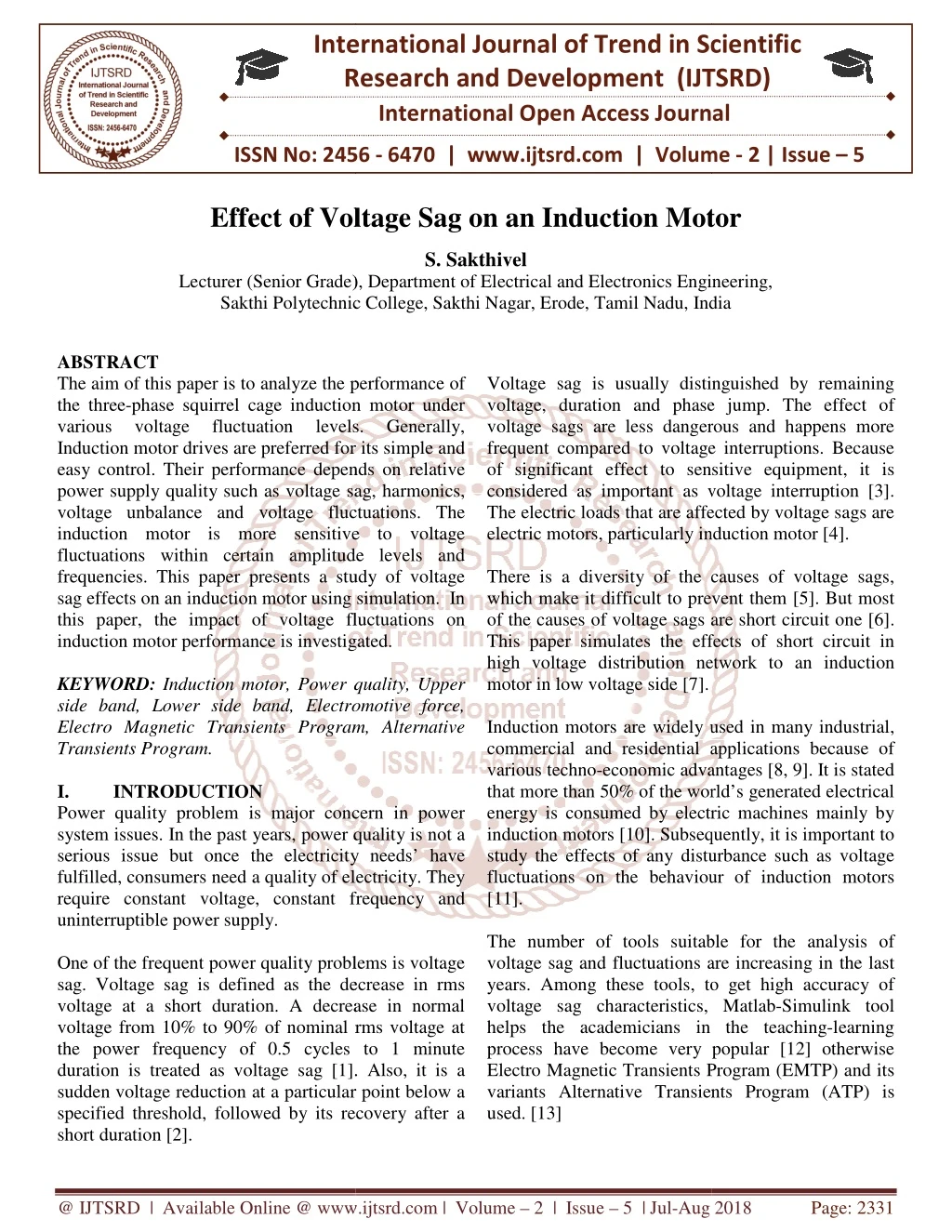
International Research Research and Development (IJTSRD) International Open Access Journal Voltage Sag on an Induction Motor S. Sakthivel Lecturer (Senior Grade), Department of Electrical and Electronics Engineering, Sakthi Polytechnic College, Sakthi Nagar, Erode, Tamil Nadu, India International Journal of Trend in Scientific Scientific (IJTSRD) International Open Access Journal ISSN No: 2456 ISSN No: 2456 - 6470 | www.ijtsrd.com | Volume 6470 | www.ijtsrd.com | Volume - 2 | Issue – 5 Effect of Voltage Sag Induction Motor Lecturer (Senior Grade), Department of Electrical and Electronics Engineering, Sakthi Polytechnic College, Sakthi Nagar, Erode, Tamil Nadu Lecturer (Senior Grade), Department of Electrical and Electronics Engineering, , India ABSTRACT The aim of this paper is to analyze the performance of the three-phase squirrel cage induction motor under various voltage fluctuation Induction motor drives are preferred for its simple easy control. Their performance depends on relative power supply quality such as voltage sag, harmonics, voltage unbalance and voltage fluctuations. The induction motor is more sensitive to voltage fluctuations within certain amplitude levels and frequencies. This paper presents a study of voltage sag effects on an induction motor using simulation. In this paper, the impact of voltage fluctuations on induction motor performance is investigated. KEYWORD: Induction motor, Power quality, Upper side band, Lower side band, Electromotive force, Electro Magnetic Transients Program, Alternative Transients Program. I. INTRODUCTION Power quality problem is major concern in power system issues. In the past years, power quality is not a serious issue but once the electricity needs’ have fulfilled, consumers need a quality of electricity. They require constant voltage, constant frequenc uninterruptible power supply. One of the frequent power quality problems is voltage sag. Voltage sag is defined as the decrease in rms voltage at a short duration. A decrease in normal voltage from 10% to 90% of nominal rms voltage at the power frequency of 0.5 cycles to 1 minute duration is treated as voltage sag [1]. Also, it is a sudden voltage reduction at a particular point below a specified threshold, followed by its recovery after a short duration [2]. Voltage sag is usually distinguished b voltage, duration and phase jump. The effect of voltage sags are less dangerous and happens more frequent compared to voltage interruptions. Because of significant effect to sensitive equipment, it is considered as important as voltage interrup The electric loads that are affected by voltage sags are electric motors, particularly induction motor [4]. There is a diversity of the causes of voltage sags, which make it difficult to prevent them [5]. But most of the causes of voltage sags are short circuit one [6]. This paper simulates the effects of short circuit in high voltage distribution network to an induction motor in low voltage side [7]. Induction motors are widely used in many industrial, commercial and residential applications various techno-economic advantages [8, 9]. It is stated that more than 50% of the world’s generated electrical energy is consumed by electric machines mainly by induction motors [10]. Subsequently, it is important to study the effects of any disturbance such as voltage fluctuations on the behaviour of induction motors [11]. The number of tools suitable for the analysis of voltage sag and fluctuations are increasing in the last years. Among these tools, to get high accuracy of voltage sag characteristics, Matlab helps the academicians in the teaching process have become very popular [12] otherwise Electro Magnetic Transients Program (EMTP) and its variants Alternative Transients Program (ATP) is used. [13] The aim of this paper is to analyze the performance of phase squirrel cage induction motor under various voltage fluctuation Induction motor drives are preferred for its simple and easy control. Their performance depends on relative power supply quality such as voltage sag, harmonics, voltage unbalance and voltage fluctuations. The induction motor is more sensitive to voltage fluctuations within certain amplitude levels and encies. This paper presents a study of voltage sag effects on an induction motor using simulation. In this paper, the impact of voltage fluctuations on induction motor performance is investigated. Voltage sag is usually distinguished by remaining voltage, duration and phase jump. The effect of voltage sags are less dangerous and happens more frequent compared to voltage interruptions. Because of significant effect to sensitive equipment, it is considered as important as voltage interruption [3]. The electric loads that are affected by voltage sags are electric motors, particularly induction motor [4]. levels. levels. Generally, Generally, There is a diversity of the causes of voltage sags, which make it difficult to prevent them [5]. But most are short circuit one [6]. This paper simulates the effects of short circuit in high voltage distribution network to an induction Induction motor, Power quality, Upper Lower side band, Electromotive force, Electro Magnetic Transients Program, Alternative Induction motors are widely used in many industrial, commercial and residential applications because of economic advantages [8, 9]. It is stated that more than 50% of the world’s generated electrical energy is consumed by electric machines mainly by induction motors [10]. Subsequently, it is important to Power quality problem is major concern in power system issues. In the past years, power quality is not a serious issue but once the electricity needs’ have fulfilled, consumers need a quality of electricity. They require constant voltage, constant frequency and turbance such as voltage fluctuations on the behaviour of induction motors The number of tools suitable for the analysis of voltage sag and fluctuations are increasing in the last years. Among these tools, to get high accuracy of eristics, Matlab-Simulink tool helps the academicians in the teaching-learning process have become very popular [12] otherwise Electro Magnetic Transients Program (EMTP) and its variants Alternative Transients Program (ATP) is One of the frequent power quality problems is voltage sag. Voltage sag is defined as the decrease in rms voltage at a short duration. A decrease in normal voltage from 10% to 90% of nominal rms voltage at quency of 0.5 cycles to 1 minute duration is treated as voltage sag [1]. Also, it is a sudden voltage reduction at a particular point below a specified threshold, followed by its recovery after a @ IJTSRD | Available Online @ www.ijtsrd.com @ IJTSRD | Available Online @ www.ijtsrd.com | Volume – 2 | Issue – 5 | Jul-Aug 2018 Aug 2018 Page: 2331
International Journal of Trend in Scientific Research and Development (IJTSRD) ISSN: 2456-6470 Using this simulation tool, complex networks and control systems of arbitrary structure can be simulated. It is having wide-range of modeling capabilities and significant features with the transient computation. A.Voltage fluctuations in an Induction Motor A voltage fluctuation is an unsystematic voltage change that happen when devices or equipment requiring a higher load are used. The voltage fluctuation effect is similar to the effects of an under voltage. The fluctuation characteristic depends on the type of connected load and power system capacity. Voltage fluctuations are caused by the connected loads which are having significant sudden or periodic variations. The fluctuating current drawn from supply causes additional voltage drops in the power system which leads to fluctuations in the supply voltage. Loads that show continuous and quick variations are the causes of voltage fluctuation. Often quick fluctuations in load currents are attributed to motor starting operations where the motor current is between 3-5 times of rated current for a short duration. If the same motor frequently starts and stops or a number of motors are started at a time, the frequency of voltage changes may create flicker in lighting system. Figure 1 illustrates voltage fluctuation with a periodical sinusoidal modulation. The voltage waveform exhibits variations in magnitude due to the fluctuating nature or intermittent operation of loads. The frequency of voltage envelope is referred as the flicker frequency. So, the frequency of fluctuation and the magnitude of fluctuation are the two important parameters of voltage fluctuations. Both of these components are important in the bad effects of voltage fluctuations. The main aim of this paper is to study the induction motor behaviour under periodical voltage fluctuations with constant amplitude. Typically induction motors are designed to tolerate a small level of voltage fluctuations. Figure 1: Voltage fluctuation with a periodical sinusoidal modulation. However, certain fluctuation levels can cause serious problems to the motor operation, which in turn may cause protection systems triggering, and ultimately leading to production loss. [14] As figure 1shows, ∆V represents the voltage magnitude variation. In figure 1, the voltage changes are shown as being modulated in a sinusoidal manner. Nevertheless, the voltage changes profile will be rectangular or irregular in shape and depends on the current drawn by the fluctuating load. [15] According to the EN50160 [16] standard, voltage fluctuations are the variations in RMS or peak value with a magnitude of less than ±10% of nominal voltage. They are characterized by the frequency of variation (fm), up to 30 Hz and magnitude (∆V). Generally, voltage fluctuations are incorporated with the flicker effect and may be the effect of fluctuations in the energy system permissibility limits are established by the standards IEC 610000-3-3 [17] and IEC 610000-3-5 [18]. Recently, PQ issues meet a new challenge for voltage fluctuation, including online monitoring system, flicker trace analysis technology, etc [19, 20]. Voltage fluctuations can be classified into, periodic voltage oscillations with constant amplitude, irregular amplitude and continuous random fluctuations. In this paper, the periodic sinusoidal voltage fluctuation with constant amplitude and with different modulating frequencies is used to study the behavior of an induction motor [21]. transmission and its and flicker mitigation @ IJTSRD | Available Online @ www.ijtsrd.com | Volume – 2 | Issue – 5 | Jul-Aug 2018 Page: 2332
International Journal of Trend in Scientific Research and Development (IJTSRD) ISSN: 2456-6470 II. Impacts of Voltage Sags on Induction Motors Induction motors characterize the most typical loads in power system applications. It consumes about 50% of the electrical energy generated in industrialized countries. The impact of voltage sag on an Induction motor is shown in figure 2. decreases, the current will increase in roughly the same proportion that the voltage decreases. For example, a 10% voltage decrease would cause a 10% load current increase. If the same motor is operating a heavy load, also there is a reduction in voltage, the load current will rise to a new value with already high current drawn, which may exceed the full-load rated current. When low voltage is applied, overheating, reduced life, starting ability and reduced pull-up and pull-out torque may occur [23]. C.High Voltage Condition High voltage on an IM pushes the magnetic portion of the motor into saturation. The concept of saturation is similar to the operation of 60 Hz transformer in 50 Hz supply system. Saturation will cause the motor to take excessive current in an effort to magnetize the iron beyond the point where magnetizing is practical. Motors can tolerate a certain increase in voltage above the mentioned rating [24]. However, extremes will cause the current to go up with a corresponding increase in heating and a shortening of motor life. Although the manufacturer provides a tolerance curve for the supply voltage, the good performance will be achieved when the rated voltage is applied to the motor. D.Effects of Voltage Imbalance When the line voltages applied to the motor terminals are not equal, as in unsymmetrical voltage sags, unbalance currents in the stator windings will occur. A small percentage of voltage unbalance makes a larger percentage of current unbalance. 3 phase motors supplied with unbalanced voltage will draw approximately 6-10 times of unbalanced current with normal value. It causes overheating and premature damage to the motors. Short duration sags will have little heating effect if it continues; will degrade the motor insulation as well as the life [25, 26]. E.Factors Affecting Voltage Sag Type of fault: It is the main factor which affects the sag characteristic. Voltage sags can be either balanced or unbalanced, depending on the causes or type of fault. If the phase voltages are equal, the sag is balanced and vice-versa. Location of fault: It has a great impact on the magnitude as well as the phase-angle jump of the sag. Figure 2: Impact of voltage sags on an Induction motor A.Negative Torque Spike Consider an Induction motor is operated in steady state condition and the supply voltage is removed and then reapplied after a short period of time. When the supply voltage is restored, the back EMF is out of phase with the supply voltage. To alter the rotor currents, the motor will decelerate, which results in negative torque transients that may reach up to 20 times the rated torque of the motor [22]. The negative torque will ultimately result in rotor shaft and winding damage if it continues. B.Low Voltage Condition Motor operation below the voltage rating reduces its efficiency, shortens lifetime and causes impulsive failure. To operate a constant mechanical load, a motor draws a specific power from the source. This power has a direct correlation to the voltage and current drawn. Thus, when supply voltage is low, the current must increase to compensate the power level to operate the load. When the current exceeds, heat begins to build up in the motor. Without timely correction, excessive heat will eventually damage the motor. Temperature T α I12t + I22t (Rr2/Rr1) Where, Rr2 = Negative sequence Rr1 = Positive sequence The connected load is a main factor to determine how much of a decrease in supply voltage a motor can handle. For a light load operating motor, if the voltage (01) @ IJTSRD | Available Online @ www.ijtsrd.com | Volume – 2 | Issue – 5 | Jul-Aug 2018 Page: 2333
International Journal of Trend in Scientific Research and Development (IJTSRD) ISSN: 2456-6470 IV. Even though we are considering the open and short circuit conditions, we should concentrate the intermediate conditions, where voltage sag exists but its magnitude is less than 100%. A 3 phase short circuit at a particular point away from motor terminals can cause the voltage sag. The final voltage sag depends on the distance between the fault location from the motor and the motor load level. In this paper, simulation results of two symmetrical voltage sags, one with a 70% decrease called deep voltage sag and the other with a 15% are considered. Figure 5 shows a stator line current after the event of 70% symmetrical voltage sag within duration of 5 cycles. The current increases at first and then its amplitude was decreased gradually after the end of magnetic transience. If voltage sag duration increases, the current will increase once again due to reduced EMFs due to the reduction in motor speed, but with 5 cycle duration, the maximum current occurred at the starting point and its magnitude is 3 times of nominal motor current. At the end of voltage sag, it may be 2 times of the nominal motor current. However, during the voltage sag, the wasted energy in motor conductors (i2dt) is 5 times of the motor when it works at 85% of rated load. Voltage Sag at Intermediate Conditions X/R ratio of the lines: With change in the X/R ratio of the line there is change in the X/R ratio of fault to source impedance which will affect the magnitude as well as phase-angle jump, Point on wave of sag initiation: The point on wave of sag initiation is the phase angle of the fundamental voltage wave at which the voltage sag starts. This angle corresponds to the angle at which the short circuit fault occurs, [27, 28]. III. Induction Motor Dynamic Model The dynamic d- q model of an electric machine shown in figure 3 is one of the common methods used to analyse induction machine performance. Parameters such as torque, stator and rotor current, rotor speed, etc. will be experimented with this model. Based on figure 1, the per-phase equivalent circuit can be converted to a side-band equivalent circuit with respect to USB and LSB components. Figure 3: Dynamic d -q model of an induction motor Mathematically, the slip at the USB and LSB field can be defined as, SUSB = {(ωUSB - ωr) / ωUSB } SLSB = {(ωLSB - ωr) / ωLSB } The dynamic simulation model of 3 phase induction motor is shown in figure 4. Figure 5: Simulation of stator current waveform during 70% of voltage sag and 85% of rated load A.Symmetrical Voltage Sag A stator current waveform after the event of 15% symmetrical voltage sag within 5 cycle duration is shown in figure 6. In this case, the motor current is approximately 20% higher than its nominal current. Figure 4: Dynamic simulation model of 3 phase Induction motor. @ IJTSRD | Available Online @ www.ijtsrd.com | Volume – 2 | Issue – 5 | Jul-Aug 2018 Page: 2334
International Journal of Trend in Scientific Research and Development (IJTSRD) ISSN: 2456-6470 The speed reduction is not sensible. The wasted energy in motor conductors is almost similar to the normal operation of motor under 85% of rated load. Figure 7 shows the motor line current waveform in a faulty phase. As seen, both voltage sag types have increased the magnitude of current waveform after the starting and end of voltage sags. In addition, the amplitude of the current waveform due to double phase sag has a higher value. Similar simulations are done in which the motor is under 85% of its rated load, but small increases in current is observed [29]. V. Simulation results The result illustrates both stator and rotor current characteristics which includes the analysis of dynamic model and the per-phase equivalent calculation, are reviewed in figure 8 and figure 9. Figure 6:Simulation of stator current waveform during 15% of voltage sag and 85% of rated load The main factor of reducing the motor life time is excessive current flowing through their windings. It causes impulsive aging in machines through increasing thermal stresses and electromagnetic effects on insulation. The severity of poor effects of excessive current on the machine is a function of current amplitude and its duration. So, high currents at very short time periods will be problematic. Also, it is noted that based on the deepness of voltage sag, the induction motor winding current may be increased impressively in starting time and end of voltage sags. B.Asymmetrical Voltage Sag When only one or two phase voltages are affected, the relevant voltage sag is called as asymmetrical. As single phase to ground and double phase short circuits are the main causes of asymmetrical voltage sags, these faults are used to simulate the asymmetrical voltage sags. Under no load condition, a relevant short circuit was applied to its terminals for about 5 cycles. (a)Stator current waveform (b)Stator current frequency spectrum Figure 8: Simulation of stator current profile under 10% voltage changes and 20 Hz modulation frequency condition Figure 7:Simulation of stator current waveform during Asymmetric voltage sags under no load (a) Rotor current waveform @ IJTSRD | Available Online @ www.ijtsrd.com | Volume – 2 | Issue – 5 | Jul-Aug 2018 Page: 2335
International Journal of Trend in Scientific Research and Development (IJTSRD) ISSN: 2456-6470 2.IEC 61000-4-11, “Testing and measurement techniques – Voltage dips, short interruptions and voltage variations immunity tests,” International Electro technical Commission. 3.M. F. Mc Granaghan, D. R. Mueller and M. J. Samotyj, “Voltage sags in industrial systems,” IEEE Trans. on Industry Applications, vol. 29, no. 2, pp. 397-403, March/April 1993. 4.J. Gocalves, J. Baptista, L. Neves and F. T. Oliveira, “Simulation of the effect of voltage transients on an ATP/EMTP,” International Renewable Energies and Power Quality, April 2009. 5.Math H. J. Bollen, “Understanding Power Quality Problems. Voltage Sags and Interruptions, ” IEEE Press, 2000, New York. 6.R. C. Dugan, M. F. Mc Granaghan, S. Santoso and H. W. Beaty, “Electrical Power Systems Quality,” 2nd ed, McGraw-Hill, 2002, New York. 7.Fikri Waskito and Channarong Banmongkol, “Simulation of the Voltage Sag Effects on an Induction Motor”, International Conference on Consumer Electronics, Communications and Networks (CECNet), IEEE Explore, 16-18 April 2011. 8.Kyung-Won Jeon, Yong-Jae Kim, and Sang-Yong Jung, “Design Characteristics Harmonics Reduction of Induction Motors for Electric Vehicle Propulsion,” Magnetics, vol. 18, no. 2, pp. 212-215, 2013. 9.R. H. C. Palácios, I. N. da Silva, A. Goedtel and W.F. Godoy, “A comprehensive evaluation of intelligent classifiers for fault identification in three-phase induction motors,” Electrical Power System Res., vol. 127, pp. 249-258, 2015. 10.K. Komeza and M. Dems, “Finite-Element and Analytical Calculations of No-Load Core Losses in Energy-Saving Induction Motors,” IEEE Transactions on Industrial Electronics, vol. 59, no. 7, pp. 2934 – 2946, July 2012. (b) Rotor current frequency spectrum Figure 9: Simulation of rotor current profile under 10% voltage changes and 20 Hz modulation frequency condition induction motor with on Conference The induction motor stator and rotor current waveforms and corresponding frequency analyses are shown in figure 8 and figure 9 when it is subjected to a 10% voltage magnitude change and 20 Hz modulation frequency. For the stator current, figures show that the modulation frequency component appears as an USB and LSB in the stator current frequency spectrum, which is centered on the fundamental frequency. The modulation frequency voltage causes the rotor current distortion. Further, the frequency analysis shows the LSB current magnitude is higher than the USB current magnitude. It is due to the motor reactance at lower frequency sideband is less than that of higher frequency sideband. VI. CONCLUSION In this paper, the performance of Induction motor due to voltage sag was studied. Also, the induction motor stator and rotor current characteristics were examined when it subjected to regular voltage fluctuations. The dynamic and per-phase model were applied to simulate the stator, rotor current variations by assuming a constant load torque. It is concluded that, based on the level and type of voltage sag, reacceleration of the motor may be difficult and consequently higher current is drawn from a source which causes thermal stresses in the motor and the 3 phase symmetrical type voltage sag is considered as the most dangerous type for an Induction motors. REFERENCES 1.IEEE Std., “1159–1995 IEEE Recommended Practice for Monitoring Electric Power Quality,” IEEE, 1995. DOI:10.1109/IEEESTD.1995.79050. of Torque Journal of 11.Morteza Ghaseminezhad, Aref Doroudi, Seyed Hossein Hosseinian and Alireza Jalilian, “An Investigation of Induction Motor Saturation under Voltage Fluctuation Conditions,” Journal of Magnetics, vol. 22, no. 2, pp. 306-314, 2017. 12.F. Jurado, N. Acero, J. Carpio and M. Castro, “Using various computer tools in electrical @ IJTSRD | Available Online @ www.ijtsrd.com | Volume – 2 | Issue – 5 | Jul-Aug 2018 Page: 2336
International Journal of Trend in Scientific Research and Development (IJTSRD) ISSN: 2456-6470 21.K. Zhao, P. Ciufo and S. Perera, "Induction motors subject to regular voltage fluctuations: Stator and rotor current analysis from a heating perspective," in ICHQP 2012, 15th IEEE International Conference on Harmonics and Quality of Power, pp. 642-648, 2012. 22.M. Ohrstrom and L. Soder, “A comparison of two methods used for voltage dip characterization,” Power Tech Conference Proceedings, IEEE Bologna, vol. 4, pp. 6, June 2003. 23.J. V. Milanovic, M. T. Aung and S. C. Vegunta, “The influence of induction motors on voltage sag propagation—Part I: Accounting for the change in sag characteristics,” IEEE Transactions on Power Delivery, vol. 23, no. 2, pp. 1063-1071, 2008. 24.E. Cowern, "The Highs and Lows of Motor Voltage," Electrical Maintenance magazine, May 1, 2000. 25.D. Dour, and P. Lim, "Resolving Voltage Quality Problems with AC Induction Motors," Energy Matters-Industrial Technologies Program, Spring 2005. 26.Malala Abubakar, “Effects of voltage sag during starting of an induction motor,” Faculty of Electrical and Electronic Engineering, Universiti Tun Hussein Onn Malaysia, January 2016. transients studies,” in 30th Annual Frontiers in Education, vol. 2, Kansas City, pp. 18 - 21, October 2000. 13.J. A Martinez and J. M. Arnendo, “Voltage Sag Analysis Using an Electromagnetic Transients Program,” IEEE Power Engineering Society Winter Meeting, vol.2, no.1, pp. 1135-1140, 1993. 14.Jos´e Baptista, Jos´e Gonc¸alves, Salviano Soares, Ant´onio Valente, Raul Morais, Jos´e Bulas-Cruz and Manuel J.C.S. Reis, “Induction motor response to periodical voltage Fluctuations,” XIX International Conference on Electrical Machines - ICEM 2010, Rome. 15.Power Quality Centre, University of Wollongong, “Voltage fluctuations in the electric supply system,” Integral Energy, Technical Note No. 7, August 2003. 16.“NP EN 50160: Voltage characteristics of electricity supplied systems,” CENELEC, 1995. 17.“IEC 61000-3-3: Electromagnetic Compatibility (EMC), Part 3: Limits-Section 3: Limitation of voltage fluctuations and flicker in low-voltage supply systems for equipment with rated current - 16A,” International Electro technical Commission, 1994. 18.“IEC 61000-3-5: Electromagnetic Compatibility (EMC), Part 3: Limits-Section 5: Limitation of voltage fluctuations and flicker in low-voltage supply systems for equipment with rated current > 16A,” International Electro technical Commission, 1995. 19.C. Vilar Moreno, H. Amaris Duarte and J. Usaola Garcia, “Propagation of flicker in electric power networks due to wind energy conversions systems,” Energy Conversion, IEEE Trans. on, vol. 17, no. 2, pp. 267 –272, Jun 2002. 20.M. Marei, E. El-Saadany and M. Salama, “An intelligent control for the dg interface to mitigate voltage flicker,” in Applied Power Electronics Conference and Exposition, 2003. APEC ’03. Eighteenth Annual IEEE, vol. 1, pp. 179 – 183, Feb 2003. Construction and by public distribution 27.A. B. Baggini, (Ed.)., “Handbook of power quality,” Chic ester: John Wiley and Sons, vol. 520, 2008. 28.O. Ipinnimo, S. Chowdhury, S. P. Chowdhury and J. Mitra, “A review of Voltage dip mitigation techniques with distributed electricity networks,” Electric Power Systems Research, vol. 103, pp. 28-36, 2013. 29.Mansour Ojaghi, Jawad Faiz, Hamid Shahrouzi and Sahar Alimohammadi, “Induction Motors Performance Study under Various Voltage Sags using Simulation,” Journal of International Conference on Electrical Machines and Systems, vol. 1, no. 3, pp. 32-39, 2012. generation in @ IJTSRD | Available Online @ www.ijtsrd.com | Volume – 2 | Issue – 5 | Jul-Aug 2018 Page: 2337