Download
1 / 5
100 likes | 128 Views
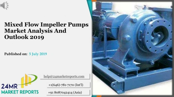
Mixed flow pump impeller is a centrifugal pump device where the transition of fluid flow takes place in both axial and radial direction. In this work a mixed flow pump impeller has been designed using CATIA V5 software tool and analyzed using the fundamentals of fluid mechanics and turbo machinery. As per many researchers there are many methods are used to design the impeller but still the optimized design of the mixed flow pump impeller blade has been a cumbersome work. The impeller blades have been designed by varying the semi cone angle. The CFD analysis is the advanced tool used in pump industry to improve the efficiency hence the CFD analysis is carried over the model to predict analytical values and to solve problems the problems that involves the fluid flow using ANSYS workbench 16.0. Because of its anti corrosive property stainless steel is used as material for impeller and water liquid used as a fluent which flow around the impeller. From the CFD analysis the velocity and pressure in the outlet is predicted. The outlet values will be useful for calculating the efficiency of the pump. B. Naresh | P. Krishna | N. Sunny Deepak | P. Laxmi Prasanna "Design and Analysis of Mixed Flow Pump Impeller" Published in International Journal of Trend in Scientific Research and Development (ijtsrd), ISSN: 2456-6470, Volume-3 | Issue-3 , April 2019, URL: https://www.ijtsrd.com/papers/ijtsrd23305.pdf Paper URL: https://www.ijtsrd.com/engineering/mechanical-engineering/23305/design-and-analysis-of-mixed-flow-pump-impeller/b-naresh<br>

E N D
International Journal of Trend in Scientific Research and Development (IJTSRD) Volume: 3 | Issue: 3 | Mar-Apr 2019 Available Online: www.ijtsrd.com e-ISSN: 2456 - 6470 Design and Analysis of Mixed Flow Pump Impeller B. Naresh1, P. Krishna2, N. Sunny Deepak2, P. Laxmi Prasanna2 1Assistant Professor, 2Student 1,2Department of Mechanical Engineering, GNIT, Rangareddy, Telangana, India How to cite this paper:B. Naresh | P. Krishna | N. Sunny Deepak | P. Laxmi Prasanna" Design and Analysis of Mixed Flow Pump Impeller" Published in International Journal of Trend in Scientific Research and Development (ijtsrd), ISSN: 2456- 6470, Volume-3 | Issue-3, April 2019, pp.1180-1184, URL: https://www.ijtsrd.c om/papers/ijtsrd23 305.pdf Copyright © 2019 by author(s) and International Journal of Trend in Scientific Research and Development Journal. This is an Open Access article distributed under the terms of the Creative Commons Attribution License (CC BY 4.0) (http://creativecommons.org/licenses/ by/4.0) INTRODUCTION A pump is a device that moves liquids or gases, sometimes slurries, by mechanical action. Mixed flow pump impeller is a centrifugal pump device where the transition of fluid flow takes place in both axial and radial direction. The fluid experiences both radial acceleration and lift and exits the impeller somewhere between 0 and 90 degrees from the axial direction. An impeller is a rotating component of a centrifugal pump which the motor that drives the pump to the fluid being pumped by accelerating the fluid outwards from the center of rotation. The velocity achieved by the impeller a variety of centrifugal pump types have been used in many different applications in industry and other technical fields. However, their design and performance prediction process are still a difficult task, due to the great number of free geometric parameters, the effect of which cannot be directly evaluated. The significant cost and time of the trial-and-error process by constructing and testing physical prototypes reduces the profit margins of the pump manufacturers. For this reason, CFD analysis is currently being used in the design and construction stage of various pump types. This article is going to describe how the design of the impeller will be and how the analysis of the impeller is carried for mixed flow and to find the numerical and graphical values of the impeller transfers into pressure when the outward movement of the fluid is confined by the pump casing. ABSTRACT Mixed flow pump impeller is a centrifugal pump device where the transition of fluid flow takes place in both axial and radial direction. In this work a mixed flow pump impeller has been designed using CATIA V5 software tool and analyzed using the fundamentals of fluid mechanics and turbo machinery. As per many researchers there are many methods are used to design the impeller but still the optimized design of the mixed flow pump impeller blade has been a cumbersome work. The impeller blades have been designed by varying the semi-cone angle. The CFD analysis is the advanced tool used in pump industry to improve the efficiency hence the CFD analysis is carried over the model to predict analytical values and to solve problems the problems that involves the fluid flow using ANSYS workbench 16.0. Because of its anti-corrosive property stainless steel is used as material for impeller and water (liquid) used as a fluent which flow around the impeller. From the CFD analysis the velocity and pressure in the outlet is predicted. The outlet values will be useful for calculating the efficiency of the pump. Keywords: CATIA V5, CFD analysis, mixed flow pump impeller, stainless steel, etc., IJTSRD23305 The experimental way of pump test can give the actual value of head developed, power rating and efficiency. But the internal flow conditions cannot be predicted by the experimental results. From the CFD analysis software and advanced post processing tools the complex flow inside the impeller can be analyzed. The complex flow characteristics like inlet pre-swirl, flow separation and outlet recirculation cannot be visualized by the experimental way of pump test. But in the case of CFD analysis the above flow characters can be visualized clearly. Moreover, design modification can be done easily and thus CFD analysis reduces the product development time and cost. Mixed flow pumps are widely used for water transportation or as cooling water pumps in power stations. Their operating range spans from full-load down to close to the shut- off head. In order to develop a reliable machine for this highly demanding operation, the behavior of the flow in the entire pump has to be predicted by a reliable computational Ramakrishnan, 2006). The numerical simulation can provide quite accurate information on the fluid behavior in the machine, and thus helps the engineer to obtain a thorough performance evaluation of a particular design. However, the challenge of improving the hydraulic efficiency requires the inverse design process, in which a significant number of alternative designs must be evaluated (Nagnostopoulos, 2006, Sedlar et al., 2009). The complex flow pattern inside the centrifugal pump is strong three dimensional with recirculation flows at inlet and exit, flow separation, transfers energy from method (Patel and @ IJTSRD | Unique Paper ID – IJTSRD23305 | Volume – 3 | Issue – 3 | Mar-Apr 2019 Page: 1180
International Journal of Trend in Scientific Research and Development (IJTSRD) @ www.ijtsrd.com eISSN: 2456-6470 cavitations. The curvatures of the blades and the rotational system have great influence on the flow field (Cheah and Lee, 2007). The meridional velocity and its effect on the performance of the pump can be improved by using proper vane geometric features (Miyauchi et al., 2004). Also, the efficiency of the impeller can be improved by changing the volute design of the impeller and by increasing the number of impeller blades (Baun and Flack, 2003) tested. Literature review Wislicensus (1965) started the design of a mixed flow pump impeller. The changes of mixed flow pump impeller were performed by Myles (1965). Busemann (1928) proposed a formula for slip velocity for a mixed flow pump. Senoo and Nakase (1972), Inoue et al. (1980) developed a design method by calculating the meridional stream line. A.J. Step an off (1967) gave a design procedure for mixed flow pump impeller. Neumann’s (1991), Gahlot and Nyiri (1993) have suggested the step-by-step design procedure for designing Mixed flow pumps. Yumiko Takayama and Hiroyoshi Watanabe (2009) presented a multi-objective optimization strategy of mixed-flow pump design by means of Three- Dimensional Inverse Design Approach. Jim- Hyuk Kim & Kwang-Yong Kim high efficiency design of mixed Bacharoudis, A. E. Filios, M.D. Mentzos and D. P. Margaris (2008) in their study, the performance of impellers with the same outlet diameter having different blade angles is thoroughly evaluated. The One-dimensional method along with empirical equations is adopted for the design of each impeller. The predicted performance curves result through the calculation of the internal flow field. Head-discharge curve play important role into different outlet angles. The influence of the outlet blade angle on the performance is verified with the CFD. The performance curve becomes smoother and flatter with the increase with the increase outlet blade angle. At nominal capacity, when the outlet blade angle was increased from 20° to 50°, the head was increased by more than 6% but the hydraulic efficiency was reduced by 4.5%. However, at high flow rates, the increase of the outlet blade angle caused a significant improvement of the hydraulic efficiency. [1] The mixed flow pump impeller was designed for discharge head developed, speed of rotation. Once the design parameters such as blade angle, blade stagger angle, blade chord length, were calculated, the development of complex shaped blades were carried out by superimposing the various blade sections one over another to satisfy blade stagger angle on the conical surface of the pump impeller. [2] Mandar TABIB et al, studied the CFD analysis of mixed flow pump derived that the computational simulation of the mixed flow pump impeller was implemented. A CFD code, the ANSYS® CFX® 12.1, was used to obtain the head and pressure, velocity streamlines. [3] It is found that the mixed flow impeller having an inlet inclined balde position on the meridoinal annulus experiences less pressure as compared to trapizoidal blade positin on the meridoinal annulus from the natural frequency analyst is also found that the values of the natural frequencies for the inlet inclined blade . [4 ]KiranPatel et al, studied the CFD analysis of mixed flow pump derived that the Head predicted by CFD analysis is higher than the test result at rated point. It also concluded that Power predicted by CFD analysis is higher at rated point to compare with the test result. [5] The optimum inlet and outlet vane angles are calculated for the existing impeller by using the empirical relations. The changes in the inlet blade angle and No. of blade change the head of the impeller. [6] Stainless Steel, due to its anti- corrosive property, was chosen as the material of construction. It was observed that the value and position of maximum Von Mises stress and the total deformation for the pump impeller was within acceptable limit and at the hub and tip section respectively. An attempt has also been made to find out the natural frequencies of the pump impeller at six different modes and was found that at higher mode the natural frequency increased. METHODOLOGY Design of impeller: The design conditions used for the design of the mixed flow pump were based on the medium specific speed impeller which has been studied extensively by Goto. The basic design conditions for the impeller are presented in Table I. This impeller was designed by using conventional techniques involving the use of curve fits to smoothly connect the blade angles between the leading ' and trailing edges. Once the design parameters such as blade angle, the development of complex shaped blades were carried out by superimposing the various blade sections one over another to satisfy blade stagger angle on the conical surface of the pump impeller. Here CATIA V5 modelling software was used for modelling the impeller. The calculation of stresses in impeller blade is extremely complicated owing to number of reasons: The complex loading characteristics and the geometry of the blade is rather complicated. To get an accurate estimation of the stresses in the blades, validation of stress values is required to be compared with the calculated values. To accomplish the above, a simplified method of validation among the calculated and numerically predicted values was carried out by replacing the twisted blades with an equivalent plate having circular cross section, which acts like a cantilever plate. The material properties and the volume of both plate and blade were kept identical. FEM convergence test was carried in the plate with different size of the element find out the optimum size of the element using ANSYS workbench 16.1. Using the optimum element sizes, numerical stress analysis for the pump impeller blades were carried out. As the mixed flow pump impeller blades have complex surfaces, before applying any force to the impeller blades, theoretical calculations were carried out for the surface force density to be applied on the pump impeller for CFD analysis. Geometric feature of the impeller was studied in detail and parameterization of impeller geometry was done. Parameterization was done by reducing number of controlling geometric variables (inlet angle, outlet angle), to investigate their individual and combined effects on the flow and the impeller performance. Then parameterization mixed flow impeller can be represented using a relatively small number of parameters; some of their values are given in Table 1. The rotation speed and the main impeller dimensions, namely the exit diameter and width D2 and b2, as well as the blade inlet and exit angles, β1 and β2, respectively, determine the nominal head and and volume flow rate of the impeller. developed procedure for flow pumps. E. C. @ IJTSRD | Unique Paper ID - IJTSRD23305 | Volume – 3 | Issue – 3 | Mar-Apr 2019 Page: 1181
International Journal of Trend in Scientific Research and Development (IJTSRD) @ www.ijtsrd.com eISSN: 2456-6470 Table 1: Design Specifications Overall diameter width of base circle Shaft curvature radius Head developed Inlet diameter Outlet diameter Eccentricity of circles Blade first angle Blade second angle Blade third angle Thickness of blade No.of blades Analysis of impeller: The use of CFD plays an important role in fluid mechanics. Due to the progress of numerical methods and computer capability, the impeller design for centrifugal pumps nowadays has been analyzed by using 3D-Navier stokes program or CFD software to predict impeller performance in advance. However, both the prediction and design cannot be done easily without sufficient information and experience. If the result from the CFD is much different from the designed value, the impeller could be redesigned before being put into real production. In this work, the mixed flow pump detailed geometric feature of the impeller was studied and parameterization of impeller geometry was done. Parameterization was done by reducing number of controlling geometric variables, facilitating the investigation of their individual or combined effects on the flow and the impeller performance. From the numerical simulation procedures, velocity contours, streamlines and velocity vector representations were generated in CFD post process. The results represented the flow behavior of the different mixing impellers and helped in explaining the experimental outcome. For the anchor impeller, the performance around the impeller regions was as in Figure 7 below. There was more contact between the fluid and the impeller as the impeller cut through the fluid. In the velocity vector diagram, it was observed that there was a zero-flow region generated behind the blades due to the relatively wide blade cross-sectional area of this impeller Walls, which then splashed back and was directed vertically and in opposite directions toward the center of the tank. There was more turbulence experienced at the impeller region, due to the large blade area. This type of impeller was not very efficient in distributing the fluid all over the tank. The generated flow is expected to cause higher concentrations of the solution in the lower parts of the tank as compared to the upper regions. Procedure to be followed to analyze the model: Importing the file: By saving the CATIA file of impeller in the stp or igs format the designed impeller part can be imported into ANSYS workbench 16.0 and the remaining process is described below. Geometry: In the geometry after generating the model the Boolean operations can be performed for 3 parts for two times. In the first operation for fig 2 and fig 3 shown above can be performed and target and tool bodies can be selected as volute casing and rotor respectively. In the second operation, for impeller body and rotor selected as tool and target bodies respectively. Meshing: After imported the model to the ANSYS workbench 16.0 we have to discretize the whole model into elements. And in element the analysis is done as per our boundary condition and the solver setup. The vertices of each element are called nodes. The accuracy of the calculation is improved as the number of elements increase. The finer the mesh betters the accuracy. Fine meshes are time and memory consuming. As a result, the number of meshes should be optimal. And here we name and segregate the inlet and outlet of the impeller. 61mm 1.8mm 20mm 24.5mm 8mm 8mm 4.47mm 30 degrees 15 degrees 10 degrees 1mm 18 From the above parameters the impeller is designed is shown in below fig 1. The arrangement blades is done on the basis of the curved angles through which the fluid flow can be carried easily and outlet flow is going to occur easily. Fig 1: Design of mixed flow pump impeller The fig. 2 depicts that the impeller is covered and provide the space to the fluid to flow easily around the circular cross- section. The rotor will be helpful to rotate the impeller in circular cross section and it is designed in such a way that CFD analysis becomes easy. This model can be removed i.e., re-arranged in such a way that the above fig. 1 can be visualized by joining the (by performing Boolean operations in CFD Analysis) both the figures so that the fluent that flows around the impeller can be seen and the effects also identified easily. Fig.2: Impeller area covered by a rotor The fig. 3 shows the body that covers impeller from external loads and takes inlet and outlet through it. Fig.3: Impeller covered by chamber (volute casing) @ IJTSRD | Unique Paper ID - IJTSRD23305 | Volume – 3 | Issue – 3 | Mar-Apr 2019 Page: 1182
International Journal of Trend in Scientific Research and Development (IJTSRD) @ www.ijtsrd.com eISSN: 2456-6470 Solution: In the result the timeline is fixed for 20 sec and streamline is given and then the results is displayed on the screen. Fig 4: Meshing of an impeller CFX Solver (Setup): CFX solver is the section where we apply the boundary conditions. With the help these assignments the calculations of the fluid dynamics are done. While solving a certain problem the solver setup will change according to the problem types. Here solver setup is changed to fluent. Then the setup is shared to fluent. Fig 8: Graph calculating the parameters RESULTS AND DISCUSSION This is mainly concerned about the results that are obtained from the FLUENT analysis. As seen in the above discussion the modified parameters for the impeller is the blade angle, number of blade and rotating speed. Efficiency, total pressure head developed and velocity is calculated in the fluent for different models. Detailed view of flow of fluid can be obtained from this fluent analysis. From these areas of flow separation can be determined and the most suitable impeller type can be selected. For easy identification of results different calculated results are tabularized. Fig 5: CFX mesh editing FLUENT solver (setup): Next step is to assign the material of the fluid that flows over the impeller in this case it is water and assign the inlet boundary conditions. The reference pressure of the impeller is given as 0 atm. The input/output boundary template is selected as pressure total inlet and mass flow at out let. The pressure total is 0 atm and the speed for machine is given as 100 rpm. in this analysis the mass flow is kept as constant and rotating speed, blade angle, and number of blades are constant. Fig 9: pressure results Fig 6: FLUENT Launcher Fig 10: velocity results CONCLUSION In this work, the mixed flow pump detailed geometric feature of the impeller was designed and analysis of impeller geometry was done. Parameterization was done by reducing number of controlling geometric variables, facilitating the investigation of their individual or combined effects on the flow and the impeller performance. Thus, CFD analysis is an Fig 7: FLUENT run calculations @ IJTSRD | Unique Paper ID - IJTSRD23305 | Volume – 3 | Issue – 3 | Mar-Apr 2019 Page: 1183
International Journal of Trend in Scientific Research and Development (IJTSRD) @ www.ijtsrd.com eISSN: 2456-6470 effective tool to calculate quickly and inexpensively the effect of design and operating parameter of pump impeller. By properly designing pump impeller the efficiency of pump can be improved. In this project the centrifugal impeller is Designed concerning all the accessible limitations utilizing a standard value as the reference, Later the item’s document are changed over to ".STP" record organize (standard trade of item document) and imported to Ansys workbench to discover disfigurement and investigative valve regarding the model’s definitions. In this project the centrifugal impeller was experienced with material steel to discover and find the CFD analysis by using static auxiliary features which are included in Ansys workbench 16.0. Table 2: Values as per the analysis REFERENCES [1]www.researchgate.net/publication/2748891FFRitFm5r LQihCFPSNPkwLNBTbVZHUAnYc5iRYaWz9emtainless_ steel_material_using_ansys. [2]JIA Rui-xuan, XU Hong. Optimal design of low specific speed mixed-flow pumps impeller. Journal of Drainage Irrigation Machinery Engineering. Vol. No.02, 2010 98- 102. [3]www.academia.edu/5773906/Design_and_SNcEH1C3U XSaTcNMHNLGNuLZqjGKbSrEMZ78L45peller [4]Yun Chuan-yuan. Numerical Calculation of Turbulent Flow, Performance Experiment Mixed-flow Pump Impeller. Transactions of the Chinese Society for Agricultural Machinery. V01.39, No.3 2008. Parameter Minimum Value Maximum Value [5]www.researchgate.net/publication/2947WVXVj2khmcc LDDH1GxGcJxFPBN4bzMLPqVsp8c5iRYaWz9ema3FMz T9Tfbu36nqwaX4KnxsxjsyALcHCY8Mzxm9ofajeP. Pressure (Pa) -3273.398 587.540 Velocity (ms^-1) 0.00 2.467 [6]www.researchgate.net/publication/2748891FFRitFm5r LQihCFPSNPkwLNBTbVZHUAnYc5iRYaWz9emtainless_ steel_material_using_ansys. @ IJTSRD | Unique Paper ID - IJTSRD23305 | Volume – 3 | Issue – 3 | Mar-Apr 2019 Page: 1184