Download
1 / 29
290 likes | 297 Views
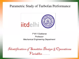
Analysis of Mixed Flow Turbofan Engine. P M V Subbarao Professor Mechanical Engineering Department. Facilitates Afterburner & Serves Defense & Space Applications …. 7. 8. 4. 5. 6h. 1. 2. 3. 6c. Mixed Flow Turbofan Engine. Condition for Ideal Mixing:. Ideal & Stable Mixer.

E N D
Analysis of Mixed Flow Turbofan Engine P M V Subbarao Professor Mechanical Engineering Department Facilitates Afterburner & Serves Defense & Space Applications ….
7 8 4 5 6h 1 2 3 6c Mixed Flow Turbofan Engine Condition for Ideal Mixing:
Ideal & Stable Mixer • Ideal Mixer : Constant Total Pressure Process. • For a stable operation of the mixer, the inlet static pressures of core flow and fan flow must be equal. • If they are not, back flow will occur in either the fan or core. The stagnation pressure ratio across the fan:
Adiabatic Mixer : 6c+6h -- 7 Adiabatic mixing process:
The Capacity of Mixed flow Jet Propulsive Power or Thrust Power: Specific Thrust based on total jet flow S
Aviation Appreciation Propulsion Efficiency
Mixed –Flow Fan : Effect of Bypass Ratio Theory of Mixing: r0p,comp=15 Mac=0.75 0,cc=5.78 Non-dimensional Specific Thrust Non-dimensional TSFC
Subsonic Operation : Mixed Turbo Fan: Mac=0.75 Fan Pressure Ratio Bypass Ratio Compressor Pressure Ratio
Design Space for Mixed Turbo Fan: Mac=2.0 Fan Pressure Ratio 2 Bypass Ratio 3 4 5 Compressor Pressure Ratio
Subsonic Operation : Mixed Turbo Fan : Mac=0.75 Fan Pressure Ratio 2 3 Specific Thrust kN.s/kg 4 5 Compressor Pressure Ratio
Fan Pressure Ratio Supersonic Operation : Mixed Turbo Fan : Mac=2.0 2 3 Specific Thrust N.s/kg 4 5 Compressor Pressure Ratio
Effect of Mach Number : Mixed Turbo Fan 2:2.0 2:0.75 Specific Thrust kN.s/kg 4:0.75 4:2.0 Compressor Pressure Ratio
Subsonic Operation : Mixed Turbo Fan : Mac=0.75 Fan Pressure Ratio 5 TSFC 4 3 2 Compressor Pressure Ratio
Supersonic Operation : Mixed Turbo Fan : Mac=2.0 5 Fan Pressure Ratio 4 3 2 TSFC Compressor Pressure Ratio
Effect of Mach Number : Mixed Turbo Fan 4 :2.0 2:2.0 Fan Pressure Ratio TSFC 4 :0.75 2:0.75 Compressor Pressure Ratio
Fan Pressure Ratio Bypass Ratio Designs for Better Fuel Economy: Subsonic Flight 5 Fan Pressure Ratio TSFC 4 TSFC 3 2 Compressor Pressure Ratio Compressor Pressure Ratio
HAL Tejas Mark 2:- Advanced Variant of LCA Tejas GE Aviation has handed over two F414-GE-INS6 engines which will eventually power Tejas MK-II by 2020 in Feb 2017. 98 kN thrust. The Tejas Mark 2 may feature an indigenously developed active electronically scanned array (AESA) fire control radar named Uttam.
TF30: Pratt and Whitney Mixed Flow Turbofan Engine The TF30−P−414 engine is a mixed−flow, dual spool afterburning low−bypass turbofan designed and manufactured by Pratt and Whitney. The engine incorporates a nine−stage low pressure compressor including a three−stage fan driven by a three−stage low pressure turbine; and a 7−stage axial flow high−pressure compressor driven by a single−stage high−pressure turbine.
SPECIFICATIONS:TF30 • Max Design Pressure Ratio: Fan: 2.14 to 1 Overall: 19.8. • Three−stage fan +Nine−stage low pressure compressor driven by a three−stage low pressure turbine; • 7−stage axial flow high−pressure compressor driven by a single−stage high−pressure turbine. • The variable−area exhaust nozzle is hydraulically actuated, 508 to 1080 sq. in • Airflow Capacity: Bypass airflow ratio: 0.878 to 1 • Max rated airflow: 242.0 lbs/s • Max rated turbine inlet: 2150F
Details of F110-GE-129 : October 2015 • The F110-GE-129 engine was selected to power the latest version of the F-15 aircraft ordered by the Republic of Korea. • The first F-15K took to the skies powered by F110 engines in March 2005. • Samsung TechWin will manufacture in Korea 78 of the 88 engines purchased by the Republic of Korea Air Force (ROKAF) for the F-15K program.
SPECIFICATIONS:F110-GE - 400 • F110-GE-129 • Thrust :129 kN • Airflow :122.4 kg/sec • Bypass ratio : 0.76 • Max Design Pressure Ratio, SLS:Fan:3.2 to 1 • Overall: 29.9 to 1 • Airflow Capacity: Max rated airflow: 270.0 lbs/s
Options for Highest Fuel Economy TSFC ropfan,opt a