Download
1 / 10
100 likes | 354 Views
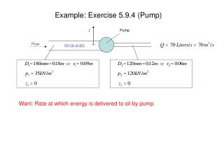
PHOENICS Impeller Pump Example. Introduction. This presentation outlines the modeling of a simple impeller pump using PHOENICS. The model shown is a transient, moving body analysis, however steady state and start-up simulations can also be run with PHOENICS. The Geometry.

E N D
PHOENICS Impeller Pump Example
Introduction This presentation outlines the modeling of a simple impeller pump using PHOENICS. The model shown is a transient, moving body analysis, however steady state and start-up simulations can also be run with PHOENICS.
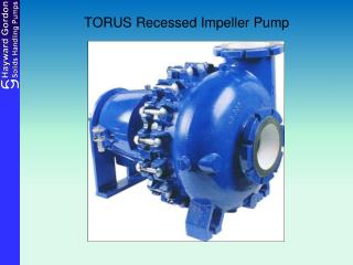
The Geometry General and detailed views of the pump geometry in the PHOENICS VR viewer. The cover is shown as transparent to aid visualisation. In this case the geometry was from stl files. Most CAD systems are capable of generating this file format. Water Outlet Water Inlet Impeller
Results - Pressure Sectional pressure profile and vectors through and around the impeller.
Results - Pressure Surface pressure profile on the impeller.
Results - Velocity Velocity vectors within the pump, showing use of the ‘near-plane’ function to view inside the impeller cross section.
Results - Velocity Detailed velocity vectors showing turbulence at the impeller tip.
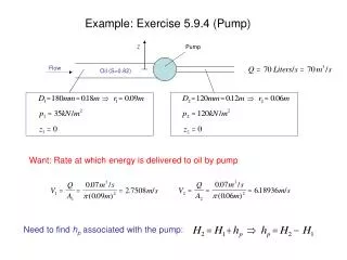
Results - Calculation From the geometry supplied the diameter of the outlet appears to be 18mm diameter. Therefore volume flow rate is given by… Area of outlet = 2.54 E-4 m Average velocity at outlet = 4.78m/s Volume flow rate = 0.00122m3/s Experimental flow rate = 0.001m3/s
END 40 High Street, Wimbledon, London, SW19 5AU Tel: 020 8947 7651 Fax:020 8879 3497 Web: www.cham.co.uk E-mail: sales@cham.co.uk