Download
1 / 4
40 likes | 45 Views
Permanent Magnet PM Brushless DC BLDC motors have been widely used in industrial drives due to their high performance, high torque density and low acoustic noise. Cogging torque in these motors is caused by the reluctance change between the stator teeth and the rotor magnets. The cogging torque invariably affects the performance of the motor by giving rise to torque ripples, vibration, speed fluctuations and acoustic noise. The main objective of the research work is to explore the design methods to reduce the cogging torque in BLDC motors. This thesis consists of two parts the first part dealing with the reshaping of Rotor Permanent Magnets and the second with the Stator Slot Modifications both for reducing the cogging torque in BLDC motors. All the proposed techniques in this thesis have been designed using CAD package MagNet. The Finite Element Analysis FEA is applied to all the proposed design methods and the CAD results are compared for cogging torque reductions. Sd. Salman | T. Rajesh | B. Archana "Brush Less Dc Motor" Published in International Journal of Trend in Scientific Research and Development (ijtsrd), ISSN: 2456-6470, Volume-4 | Issue-1 , December 2019, URL: https://www.ijtsrd.com/papers/ijtsrd29804.pdf Paper URL: https://www.ijtsrd.com/engineering/electrical-engineering/29804/brush-less-dc-motor/sd-salman<br>

E N D
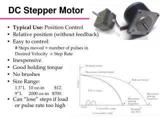
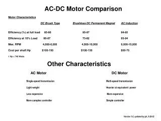
International Journal of Trend in Scientific Research and Development (IJTSRD) Volume 4 Issue 1, December 2019 Available Online: www.ijtsrd.com e-ISSN: 2456 – 6470 Brush Less Dc Motor Sd. Salman1, T. Rajesh1, B. Archana2 1UG Student, 2Associative Professor, 1,2Department of Electrical and Electronics Engineering, Audisankara College of Engineering and Technology, Gudur, Andhra Pradesh, India ABSTRACT Permanent Magnet (PM) Brushless DC (BLDC) motors have been widely used in industrial drives due to their high performance, high torque density and low acoustic noise. Cogging torque in these motors is caused by the reluctance change between the stator teeth and the rotor magnets. The cogging torque invariably affects the performance of the motor by giving rise to torque ripples, vibration, speed fluctuations and acoustic noise. The main objective of the research work is to explore the design methods to reduce the cogging torque in BLDC motors. This thesis consists of two parts; the first part dealing with the reshaping of Rotor Permanent Magnets and the second with the Stator Slot Modifications both for reducing the cogging torque in BLDC motors. All the proposed techniques in this thesis have been designed using CAD package MagNet. The Finite Element Analysis (FEA) is applied to all the proposed design methods and the CAD results are compared for cogging torque reductions. KEYWORDS: Stator Rotor working principle electrical commutation How to cite this paper: Sd. Salman | T. Rajesh | B. Archana "Brush Less Dc Motor" Published in International Journal of Trend in Scientific Research and Development (ijtsrd), ISSN: 2456- 6470, Volume-4 | Issue-1, December 2019, pp.1062-1065, www.ijtsrd.com/papers/ijtsrd29804.pdf Copyright © 2019 by author(s) and International Journal of Trend in Scientific Research and Development Journal. This is an Open Access article distributed under the terms of the Creative Commons Attribution License (CC (http://creativecommons.org/licenses/by /4.0) IJTSRD29804 URL: BY 4.0) INRODUCTION A brushless DC motor consists of a rotor in form of a permanent magnet and stator in form of polyphase armature windings. It differs from conventional dc motor in such that it doesn’t contains brushes and the commutation is done using electrically, using a electronic drive to feed the stator windings. Brushless DC motors (BLDC) are an invaluable part of industry today. Use of these motors can save nearly any industry a great deal of time and money under the right circumstances. The BLDC motor actually represents the end, or at least the most recent end result, of a long evolution of motor technology. Before there were brushless DC motors there were brushed DC motors, which were brought on in part to replace the less efficient AC induction motors that came before. The brush DC motor was invented all the way back in 1856 by famed German inventor and industrialist Ernst Werner Von Siemens. Von Siemens is so famous that the international standard unit of electrical conductance is named after him. Von Siemens studied electrical engineering after leaving the army and produced many contributions to the world of electrical engineering, including the first electric elevator in 1880. Von Siemens's brush DC motor was fairly rudimentary and was improved upon by Harry Ward Leonard, who nearly perfected the first effective motor control system near the end of the 19th century. In the year of 1873 Zenobe Gramme invented the modern DC motor. This system used a rheostat to control the current in the field winding, which resulted in adjusting the output voltage of the DC generator, which in turn adjusted the motor speed. The Ward Leonard system remained in place all the way until 1960, when the Electronic Regulator Company's thyristor devices produced solid state controllers that could convert AC power to rectified DC power more directly. It supplanted the Ward Leonard system due to its simplicity and efficiency. CONSTRUCTION BLDC motors can be constructed in different physical configurations. Depending on the stator windings, these can be configured as single-phase, two-phase, or three- phase motors. However, three-phase BLDC motors with permanent magnet rotor are most commonly used. The construction of this motor has many similarities of three phase induction motor as well as conventional DC motor. @ IJTSRD | Unique Paper ID – IJTSRD29804 | Volume – 4 | Issue – 1 | November-December 2019 Page 1062
International Journal of Trend in Scientific Research and Development (IJTSRD) @ www.ijtsrd.com eISSN: 2456-6470 Basically a BLDC motor can be constructed in two ways- by placing the rotor outside the core and the windings in the core and another by placing the windings outside the core. In the former arrangement, the rotor magnets act as a insulator and reduce the rate of heat dissipation from the motor and operates at low current. It is typically used in fans. In the latter arrangement, the motor dissipates more heat, thus causing an increase in its torque. It is used in hard disk drives. Stator of a BLDC motor made up of stacked steel laminations to carry the windings. These windings are placed in slots which are axially cut along the inner periphery of the stator. These windings can be arranged in either star or delta. However, most BLDC motors have three phase star connected stator. Each winding is constructed with numerous interconnected coils, where one or more coils are placed in each slot. In order to form an even number of poles, each of these windings is distributed over the stator periphery. Ferrite magnets are inexpensive, however they have a low flux density for a given volume. Rare earth alloy magnets are commonly used for new designs. Some of these alloys are Samarium Cobalt (SmCo), Neodymium (Nd), and Ferrite and Boron (NdFeB). The rotor can be constructed with different core configurations such as the circular core with permanent magnet on the periphery, circular core with rectangular magnets, etc. BLDC 4 Pole 2 Phase Motor Operation The brushless DC motor is driven by an electronic drive which switches the supply voltage between the stator windings as the rotor turns. The rotor position is monitored by the transducer (optical or magnetic) which supplies information to the electronic controller and based on this position, the stator winding to be energized is determined. This electronic drive consists of transistors (2 for each phase) which are operated via a microprocessor. The stator must be chosen with the correct rating of the voltage depending on the power supply capability. For robotics, automotive and small actuating applications, 48 V or less voltage BLDC motors are preferred. For industrial applications and automation systems, 100 V or higher rating motors are used. Rotor BLDC motor incorporates a permanent magnet in the rotor. The number of poles in the rotor can vary from 2 to 8 pole pairs with alternate south and north poles depending on the application requirement. In order to achieve maximum torque in the motor, the flux density of the material should be high. A proper magnetic material for the rotor is needed to produce required magnetic field density. BLDC-DC The magnetic field generated by the permanent magnets interacts with the field induced by the current in the stator @ IJTSRD | Unique Paper ID – IJTSRD29804 | Volume – 4 | Issue – 1 | November-December 2019 Page 1063
International Journal of Trend in Scientific Research and Development (IJTSRD) @ www.ijtsrd.com eISSN: 2456-6470 windings, creating a mechanical torque. The electronic switching circuit or the drive switches the supply current to the stator so as to maintain a constant angle 0 to 90 degrees between the interacting fields. Hall Sensors are mostly mounted on the stator or on the rotor. When the rotor passes through the hall sensor, based on the North or South Pole, it generates a high or low signal. Based on the combination of these signals, the winding to be energized is defined. In order to keep the motor running, the magnetic field produced by the windings should shift position, as the rotor moves to catch up with the stator field. High signals whenever the rotor poles pass near to it. The exact commutation sequence to the stator winding can be determined based on the combination of these three sensor’s response OPERATION AND WORKING PRINCIPLE OF BRUSH LESS DC MOTOR What is a Brushless DC motor (BLDC)? A brushless DC motor (known as BLDC) is a permanent magnet synchronous electric motor which is driven by direct current (DC) electricity and it accomplishes electronically controlled commutation system (commutation is the process of producing rotational torque in the motor by changing phase currents through it at appropriate times) instead of a mechanically commutation system. BLDC motors are also referred as trapezoidal permanent magnet motors. Unlike conventional brushed type DC motor, wherein the brushes make the mechanical contaccommutator on the rotor so as to form an electric path between a DC electric source and rotor armature windings, BLDC motor employs electrical commutation with permanent magnet rotor and a stator with a sequence of coils. In this motor, permanent magnet (or field poles) rotates and current carrying conductors are fixed. The armature coils are switched electronically by transistors or silicon controlled rectifiers at the correct rotor position in such a way that armature field is in space quadrature with the rotor field poles. Hence the force acting on the rotor causes it to rotate. Hall sensors or rotary encoders are most commonly used to sense the position of the rotor and are positioned around the stator. The rotor position feedback from the sensor helps to determine when to switch the armature current. This electronic commutation arrangement eliminates the commutator arrangement and brushes in a DC motor and hence more reliable and less noisy operation is achieved. Due to the absence of brushes BLDC motors are capable to run at high speeds. The efficiency of BLDC motors is typically 85 to 90 percent, whereas as brushed type DC motors are 75 to 80 percent efficient. There are wide varieties of BLDC motors available ranging from small power range to fractional horsepower, integral horsepower and large power ranges. BLDC motor works on the principle similar to that of a conventional DC motor, i.e., the Lorentz force law which states that whenever a current carrying conductor placed in a magnetic field it experiences a force. As a consequence of reaction force, the magnet will experience an equal and opposite force. In case BLDC motor, the current carrying conductor is stationary while the permanent magnet moves. When the stator coils are electrically switched by a supply source, it becomes electromagnet and starts producing the uniform field in the air gap. Though the source of supply is DC, switching makes to generate an AC voltage waveform with trapezoidal shape. Due to the force of interaction between electromagnet stator and permanent magnet rotor, the rotor continues to rotate. Consider the figure below in which motor stator is excited based on different switching states. With the switching of In a 4 pole, 2 phase brushless dc motor, a single hall sensor is used, which is embedded on the stator. As the rotor rotates, the hall sensor senses the position and develops a high or low signal, depending on the pole of the magnet (North or South). The hall sensor is connected via a resistor to the transistors. When a high voltage signal occurs at the output of the sensor, the transistor connected to coil A starts conducting, providing the path for the current to flow and thus energizing coil A. The capacitor starts charging to the full supply voltage. When the hall sensor detects a change in polarity of the rotor, it develops a low voltage signal at its output and since the transistor 1 doesn’t get any supply, it is in cutoff condition. The voltage developed around the capacitor is Vcc, which is the supply voltage to the 2nd transistor and coil B is now energized, as current passes through it. BLDC motors have fixed permanent magnets, which rotate and a fixed armature, eliminating the problems of connecting current to the moving armature. And possibly more poles on the rotor than the stator or reluctance motors. The latter may be without permanent magnets, just poles that are induced on the rotor then pulled into arrangement by timed stator windings. An electronic controller replaces the brush/commutator assembly of the brushed DC motor, which continually switches the phase to the windings to keep the motor turning. The controller performs comparative timed power distribution by using a solid-state circuit instead of the brush/commutator system. HALL SENSORS Hall sensor provides the information to synchronize stator armature excitation with rotor position. Since the commutation of BLDC motor is controlled electronically, the stator windings should be energized in sequence in order to rotate the motor. Before energizing a particular stator winding, acknowledgment of rotor position is necessary. So the Hall Effect sensor embedded in stator senses the rotor position. Most BLDC motors incorporate three Hall sensors which are embedded into the stator. Each sensor generates Low and @ IJTSRD | Unique Paper ID – IJTSRD29804 | Volume – 4 | Issue – 1 | November-December 2019 Page 1064
International Journal of Trend in Scientific Research and Development (IJTSRD) @ www.ijtsrd.com eISSN: 2456-6470 ?Quite operation (or low noise) due to absence of brushes DISADVANTAGES OF BLDC ?These motors are costly ?Electronic controller required control this motor is expensive ?Not much availability of many integrated electronic control solutions, especially for tiny BLDC motors ?Requires complex drive circuitry ?Need of additional sensors APPLICATIONS OF BLDC Brushless DC Motors (BLDC) are used for a wide variety of application requirements such as varying loads, constant loads and positioning applications in the fields of industrial control, automotive, aviation, automation systems, health care equipments, etc. Some specific applications of BLDC motors are ?Computer hard drives and DVD/CD players ?Electric vehicles, hybrid vehicles, and electric bicycles ?Industrial robots, CNC machine tools, and simple belt driven systems ?Washing machines, compressors and dryers ?Fans, pumps and blowers CONCLUSION The direct power control (DPC) method for speed/power control of BLDC motor has been studied in this study. DPC method is similar to direct torque control (DTC) method that have all advantages of DTC. Moreover, DPC is less sensitive to the motor model's parameters. One major advantage of DPC method compared to DTC method, that it can easily estimate actual power of the motor as feedback for control system. Actual power can be easily measured through voltage and current in a real system. Simulation results show that reference speed and reference power has a good response load torque. In proposed DPC method, the input power of the motor has been considered as feedback that includes electrical and mechanical losses. To control output power of the motor, losses should be included which needs more calculations. DPC-based BLDC drive system can be used also in regenerative braking systems in automotive applications. REFERENCES [1]P. C. Krause O. Wasynozuk, and S. D. Sudhoff, Analysis of Electric Machinery and Drive Systems, IEEE Press, Second Edition, 2002. windings as High and Low signals, corresponding winding energized as North and South poles. The permanent magnet rotor with North and South poles align with stator poles causing motor to rotate. Observe that motor produces torque because of the development of attraction forces (when North-South or South-North alignment) and repulsion forces (when North- North or South-South alignment). By This motor move Here, one might get a question that how we know which stator coil should be energized and when to do. This is because; the motor continuous rotation depends on the switching sequence around the coils. As discussed above that Hall sensors give shaft position feedback to the electronic controller unit. Based on this signal from sensor, the controller decides particular coils to energize. Hall-effect sensors generate Low and High level signals whenever rotor poles pass near to it. These signals determine the position of the shaft. ADVANTAGES OF BLDC BLDC motor has several advantages over conventional DC motors and some of these are ?It has no mechanical commutator and associated problems ?High efficiency due to the use of permanent magnet rotor ?High speed of operation even in loaded and unloaded conditions due to the absence of brushes that limits the speed ?Smaller motor geometry and lighter in weight than both brushed type DC and induction AC motors ?Long life as no inspection and maintenance is required for commutator system ?Higher dynamic response due to low inertia and carrying windings in the stator ?Less electromagnetic interference [2]M. Cunkas, and O. Aydogdu, “Realization of Fuzzy Logic Controlled Brushless DC Motor Drives Using Matlab/Simulink”, Mathematical and Computional Applications, vol. 15, (2), pp.218-229, 2010. [3]F. Rodriguez, and A. Emadi, “A Novel Digital Control Technique for Brushless DC Motor Drives”, IEEE Trans. on Industrial Electronics, vol. 54, no. 5, pp. 2365-2373, 2007. @ IJTSRD | Unique Paper ID – IJTSRD29804 | Volume – 4 | Issue – 1 | November-December 2019 Page 1065