Download
1 / 5
50 likes | 181 Views
This paper describes the implementation of electronic scientific calculator using Arduino. The mathematical process for scientific calculation processes are based on the digital electronic technology. The calculator takes input from a user in real time via a keypad and displays output on a LCD display module. The control, arithmetic algorithm and calculation functions are performed using a Arduino Mega 2560. The prototype of the system is configured and the simulation results for basic mathematical functions and some scientific functions of calculator are expressed with the help of Proteus simulation software. And then the experimental results are tested with the constructed calculator circuit. Ma Hnin Yu Myaing | Ma Naing "Arduino Based Scientific Calculator" Published in International Journal of Trend in Scientific Research and Development (ijtsrd), ISSN: 2456-6470, Volume-3 | Issue-5 , August 2019, URL: https://www.ijtsrd.com/papers/ijtsrd26395.pdf Paper URL: https://www.ijtsrd.com/engineering/electronics-and-communication-engineering/26395/arduino-based-scientific-calculator/ma-hnin-yu-myaing<br>

E N D
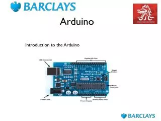
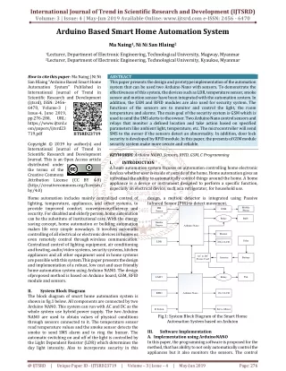
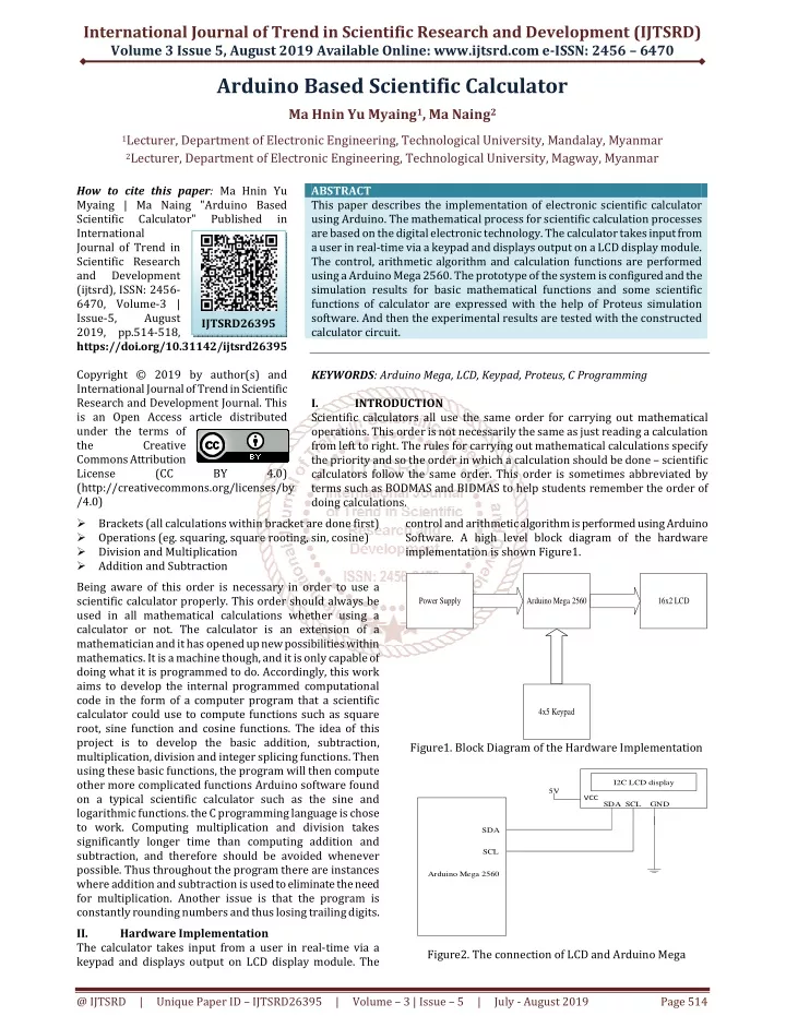
International Journal of Trend in Scientific Research and Development (IJTSRD) Volume 3 Issue 5, August 2019 Available Online: www.ijtsrd.com e-ISSN: 2456 – 6470 Arduino Based Scientific Calculator Ma Hnin Yu Myaing1, Ma Naing2 1Lecturer, Department of Electronic Engineering, Technological University, Mandalay, Myanmar 2Lecturer, Department of Electronic Engineering, Technological University, Magway, Myanmar How to cite this paper: Ma Hnin Yu Myaing | Ma Naing "Arduino Based Scientific Calculator" International Journal of Trend in Scientific Research and Development (ijtsrd), ISSN: 2456- 6470, Volume-3 | Issue-5, August 2019, pp.514-518, https://doi.org/10.31142/ijtsrd26395 Copyright © 2019 by author(s) and International Journal of Trend in Scientific Research and Development Journal. This is an Open Access article distributed under the terms of the Creative Commons Attribution License (CC (http://creativecommons.org/licenses/by /4.0) ?Brackets (all calculations within bracket are done first) ?Operations (eg. squaring, square rooting, sin, cosine) ?Division and Multiplication ?Addition and Subtraction Being aware of this order is necessary in order to use a scientific calculator properly. This order should always be used in all mathematical calculations whether using a calculator or not. The calculator is an extension of a mathematician and it has opened up new possibilities within mathematics. It is a machine though, and it is only capable of doing what it is programmed to do. Accordingly, this work aims to develop the internal programmed computational code in the form of a computer program that a scientific calculator could use to compute functions such as square root, sine function and cosine functions. The idea of this project is to develop the basic addition, subtraction, multiplication, division and integer splicing functions. Then using these basic functions, the program will then compute other more complicated functions Arduino software found on a typical scientific calculator such as the sine and logarithmic functions. the C programming language is chose to work. Computing multiplication and division takes significantly longer time than computing addition and subtraction, and therefore should be avoided whenever possible. Thus throughout the program there are instances where addition and subtraction is used to eliminate the need for multiplication. Another issue is that the program is constantly rounding numbers and thus losing trailing digits. II. Hardware Implementation The calculator takes input from a user in real-time via a keypad and displays output on LCD display module. The ABSTRACT This paper describes the implementation of electronic scientific calculator using Arduino. The mathematical process for scientific calculation processes are based on the digital electronic technology. The calculator takes input from a user in real-time via a keypad and displays output on a LCD display module. The control, arithmetic algorithm and calculation functions are performed using a Arduino Mega 2560. The prototype of the system is configured and the simulation results for basic mathematical functions and some scientific functions of calculator are expressed with the help of Proteus simulation software. And then the experimental results are tested with the constructed calculator circuit. KEYWORDS:Arduino Mega, LCD, Keypad, Proteus, C Programming I. INTRODUCTION Scientific calculators all use the same order for carrying out mathematical operations. This order is not necessarily the same as just reading a calculation from left to right. The rules for carrying out mathematical calculations specify the priority and so the order in which a calculation should be done – scientific calculators follow the same order. This order is sometimes abbreviated by terms such as BODMAS and BIDMAS to help students remember the order of doing calculations. control and arithmetic algorithm is performed using Arduino Software. A high level block diagram of the hardware implementation is shown Figure1. Published in IJTSRD26395 BY 4.0) Power Supply Arduino Mega 2560 16x2 LCD 4x5 Keypad Figure1. Block Diagram of the Hardware Implementation I2C LCD display 5V VCC SDA SCL GND SDA SCL Arduino Mega 2560 Figure2. The connection of LCD and Arduino Mega @ IJTSRD | Unique Paper ID – IJTSRD26395 | Volume – 3 | Issue – 5 | July - August 2019 Page 514
International Journal of Trend in Scientific Research and Development (IJTSRD) @ www.ijtsrd.com eISSN: 2456-6470 III. Figure3 shows the overall circuit diagram of the scientific calculator. The system includes Arduino Mega 2560, 4x5 keypad, 16x2 LCD display and other peripheral circuit components. The Arduino Mega is used as arithmetic logic unit and all calculation function perform. And then the result displays on LCD. Each part of the circuit and their connection to Arduino are described in below. Overall Circuit Operation Figure3. Overall Circuit Diagram IV. The basic calculation flowchart of arithmetic operations and all other operations of calculator are carried out can be found in the following figures. Firstly start the program, define the input/output pins and initialize I2C LCD display. Pin connection between keypad and Arduino board are described in Figure. The result is evaluated depending on the value stored in Arduino. If the user press the button number 40, the Arduino knows as addition operation. And then add two operands and display the result on LCD. Other operations are also evaluated in this manner. Flowchart of the System Operation Start Define I/O Initialize I2C LCD C Read First Button Read Operation Button Read Second Button Read Equal Button Yes Addition? Add two number Display Result No Yes Subtract two number Subtraction? Display Result No C A Figure4. Flowchart of Scientific Calculator Program @ IJTSRD | Unique Paper ID – IJTSRD26395 | Volume – 3 | Issue – 5 | July - August 2019 Page 515
International Journal of Trend in Scientific Research and Development (IJTSRD) @ www.ijtsrd.com eISSN: 2456-6470 A C Yes Multiplication? Multiply two number Display Result No Yes Division? Divide two number Display Result No Yes Square? Square the number No Display Result Yes Square Root the number Square Root? Display Result No C B Figure5. Flowchart of Scientific Calculator Program C B Yes Take Sine function of the number Sine? No Display Result Yes Take Cosine function of the number Cosine? No Display Result Clear LCD Yes C Read again? No End Figure6. Flowchart of Scientific Calculator Program @ IJTSRD | Unique Paper ID – IJTSRD26395 | Volume – 3 | Issue – 5 | July - August 2019 Page 516
International Journal of Trend in Scientific Research and Development (IJTSRD) @ www.ijtsrd.com eISSN: 2456-6470 V. All of first, the calculator circuit is designed and the calculation program is implemented. After that the calculator circuit is simulated using Proteus software. The schematic diagram of the main components of the calculator including the Arduino circuit is drawn in the Proteus software and then run the simulator program. A screenshot of the Proteus schematic capture and interactive simulation test is shown in Figure7and Figure8. After testing the calculator function with the Proteus Software the small model of the system is configured as shown in Figure9 and Figure10. Basic mathematical functions and some scientific functions can calculate in this constructed calculator. In this system, basic mathematical functions and scientific functions can be calculated. These functions are as follows: 1.Addition 2.Subtraction 3.Multiplication 4.Division 5.Square 6.Square root 7.Sine 8.Cosine Results Figure7. Screenshot of the Proteus Schematic Capture Figure8. Simulation Result of Addition Function @ IJTSRD | Unique Paper ID – IJTSRD26395 | Volume – 3 | Issue – 5 | July - August 2019 Page 517
International Journal of Trend in Scientific Research and Development (IJTSRD) @ www.ijtsrd.com eISSN: 2456-6470 Figure9. Photo of the Constructed Calculator Circuit Figure10. Experimental Result of “Addition” Function VI. This scientific calculator contains the basic arithmetic operations and some scientific functions that can be used easily. Scientific calculator all use the same order for carrying out mathematical operations. This order is not necessarily the same as just reading a calculation from left to right. There are two types of scientific calculator, the most recent type being algebraic scientific calculators. Algebraic scientific calculators allow the users to type in calculations in the order in which they have been written down. Older scientific calculators need users to press the mathematical operation key after they have entered the number. For example to find the Sine of ninety, in algebraic scientific calculator it must be pressed [SINE, 90, =]. In non algebraic scientific calculator, it is need to press [90, SINE, =]. In this study, non algebraic type scientific calculator is developed. This research aims to develop the Arduino based scientific calculator that can use to compute the basic mathematical functions and some scientific functions such as square, square root, sine function and cosine function. The system is demonstrated with a small model which is composed of LCD, a keypad and the Arduino Mega. VII. Conclusion This paper aims to develop the Arduino based scientific calculator that can use to compute the basic mathematical functions and some scientific functions such as square, square root, sine function and cosine function. The system is demonstrated with a small model which is composed of LCD, a keypad and the Arduino Mega. The code is as easily programmed as possible and that the program is to be as efficient as possible at computing the functions. In theory Discussions and through all practical testing, it is found that the calculations that are output are accurate to the two significant Figure requirement. It is extremely unlikely for any realistic design of a commercial calculator to use a Arduino Mega Board. The role and operation of Arduino in scientific calculator are explained. This focus on successful algorithm implementation that could properly handle all the cases of calculation functions. VIII. REFERENCES [1][18Ano1] Anonymous, Mega2560, 2018.http://www.ard-uino.cc/en/Main /ArduinoBoard Mega2560?setlang [2][18Ano2] Anonymous, Arduino-PinMapping 2560, 2018.http://www.arduino.cc/en/Hacking/PinMapping 2560 [3][17Tar] Tarun Agarwal, Different Types of Arduino Boards, 2017. http://www. elprocus. com/different- types-of-arduino boards/ [4][13Wik] Wikipedia: https://en.wikipedia.org/wiki/Push-button [5][12Ano] Anonymous, Serial I2C 1602 16x2 Character LCD Module, 2012.www. Serial_I2C_1602_16x2_Character_LCD_Module [6][08Ano] Anonymous, LCD - Liquid Crystal Display tutorial, http://www.microcontrollerboard.com/lcd.html [7][06Ano] Anonymous, Liquid Crystal Display (LCD), 2006.http://www.chipdoc.com/datasheets/liquidcryst aldisplay.html Arduino–ArduinoBoard Push-button, 2013. geeetech.com/ 2008. @ IJTSRD | Unique Paper ID – IJTSRD26395 | Volume – 3 | Issue – 5 | July - August 2019 Page 518