Download
1 / 5
60 likes | 85 Views
This paper presents the design and prototype implementation of the automation system that can be used two Arduino Nano with sensors. To demonstrate the effectiveness of this system, the devices such as LDR, temperature sensor, smoke sensor and motion sensor have been integrated with the automation system. In addition, the GSM and RFID modules are also used for security system. The functions of the sensors are to monitor and control the light, the room temperature and alarms. The main goal of the security system is GSM which is used to send the SMS alerts to the owner. Two Arduino Nano control sensors and relays that monitor a defined location and take action based on specified parameters like ambient light, temperature, etc. The microcontroller will send SMS to the owner if the sensors detect an abnormality. In addition, door lock security is developed by RFID module. In this paper, the presents of GSM module security system make more secure and reliable. Ma Naing | Ni Ni San Hlaing "Arduino Based Smart Home Automation System" Published in International Journal of Trend in Scientific Research and Development (ijtsrd), ISSN: 2456-6470, Volume-3 | Issue-4 , June 2019, URL: https://www.ijtsrd.com/papers/ijtsrd23719.pdf Paper URL: https://www.ijtsrd.com/engineering/electronics-and-communication-engineering/23719/arduino-based-smart-home-automation-system/ma-naing<br>

E N D
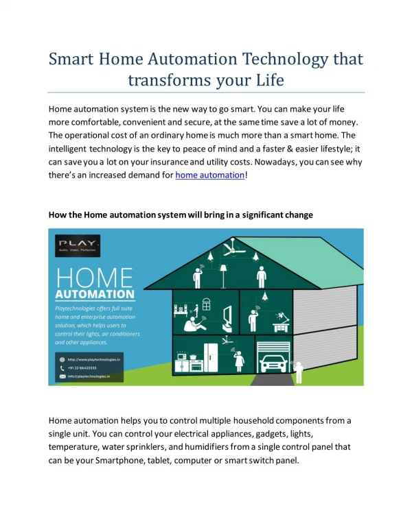
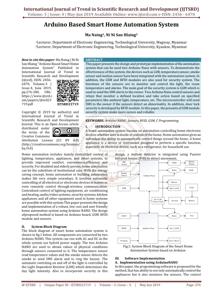
International Journal of Trend in Scientific Research and Development (IJTSRD) Volume: 3 | Issue: 4 | May-Jun 2019 Available Online: www.ijtsrd.com e-ISSN: 2456 - 6470 Arduino Based Smart Home Automation System Ma Naing1, Ni Ni San Hlaing2 1Lecturer, Department of Electronic Engineering, Technological University, Magway, Myanmar 2Lecturer, Department of Electronic Engineering, Technological University, Kyaukse, Myanmar How to cite this paper: Ma Naing | Ni Ni San Hlaing "Arduino Based Smart Home Automation System" Published in International Journal of Trend in Scientific Research and Development (ijtsrd), ISSN: 2456- 6470, Volume-3 | Issue-4, June 2019, pp.276-280, URL: https://www.ijtsrd.c om/papers/ijtsrd23 719.pdf Copyright © 2019 by author(s) and International Journal of Trend in Scientific Research and Development Journal. This is an Open Access article distributed under the terms of the Creative Commons Attribution License (CC BY 4.0) (http://creativecommons.org/licenses/ by/4.0) Home automation includes mainly centralized control of lighting, temperature, appliances, and other systems, to provide improved comfort, convenience,efficiency and security. For disabled and elderly person, home automation can be the substitute of institutional care. With the energy saving concept, home automation or building automation makes life very simple nowadays. It involves automatic controlling of all electrical or electronic devices in homes or even remotely control through wireless communication. Centralized control of lighting equipment, air conditioning and heating, audio/video systems, security systems, kitchen appliances and all other equipment used in home systems are possible with this system.This paper presents the design and implementation of a robust, low cost and user friendly home automation system using Arduino NANO. The design ofproposed method is based on Arduino board, GSM, RFID module and sensors. II. System Block Diagram The block diagram of smart home automation system is shown in fig.1 below. All components are connected by two Arduino NANO. This system can run with AC and DC as the whole system use hybrid power supply. The two Arduino NANO are used to obtain values of physical conditions through sensors connected to it. The temperature sensor read temperature values and the smoke sensor detects the smoke to send SMS alarm and to ring the buzzer. The automatic switching on and off of the light is controlled by the Light Dependent Resistor (LDR) which determines the day light intensity. Also to incorporate security in this ABSTRACT This paper presents the design and prototype implementation of the automation system that can be used two Arduino Nano with sensors. To demonstrate the effectiveness of this system, the devices such as LDR, temperature sensor, smoke sensor and motion sensor have been integrated with the automation system. In addition, the GSM and RFID modules are also used for security system. The functions of the sensors are to monitor and control the light, the room temperature and alarms. The main goal of the security system is GSM which is used to send the SMS alerts to the owner. Two Arduino Nano control sensors and relays that monitor a defined location and take action based on specified parameters like ambient light, temperature, etc. The microcontroller will send SMS to the owner if the sensors detect an abnormality. In addition, door lock security is developed by RFID module. In this paper, the presents of GSM module security system make more secure and reliable. KEYWORDS: Arduino NANO, Sensors, RFID, GSM, C Programming I. INTRODUCTION A home automation system focuses on automation controlling home electronic devices whether user is inside or outside of the home. Home automation gives an individual the ability to automatically control things around the home. A home appliance is a device or instrument designed to perform a specific function, especially an electrical device, such as a refrigerator, for household use. design, a motion detector is integrated using Passive Infrared Sensor (PIR) to detect movement. PIR Sensor IJTSRD23719 Mobile Phone GSM Relay Bulb Smoke Sensor Arduino Nano Buzzer Solar LDR 20× 4 LCD AC to DC Power Card Inverter Battery Fan LM35 Relay RFID Arduino Nano 16× 2 LCD D button Servo Motor Fig.1: System Block Diagram of the Smart Home Automation System based on Arduion III. A.Implementation using ArduinoNANO In this paper, the programming software is proposed for the method, that has ability to not only automatically control the appliances but it also monitors the sensors. The control Software Implementation @ IJTSRD | Unique Paper ID - IJTSRD23719 | Volume – 3 | Issue – 4 | May-Jun 2019 Page: 276
International Journal of Trend in Scientific Research and Development (IJTSRD) @ www.ijtsrd.com eISSN: 2456-6470 system has the ability to perform the full responsibilities. The programming software of the system is Arduino C programming software. A program is text that user write using a programming language that containsbehaviours that need a processor to acquire. It basically creates a way of handling inputs and producing outputs according to these behaviours. It is often defined as a general purpose programming language and is indeed one of the most used languages of all times.20×4 I2C LCD and 16×4 I2C LCD are used to show the condition of door, light, the value of temperature and fire condition. 20×4 LCD has 20 columns and 4 rows and 16×2 LCD has 16 columns and 2 rows. Both LCD have I2C serial pin to connect with Arduino. LCD device is connected with I2C device to reduce pin connection of LCD. I2C device has SDA and SCL pin for serial communication. The other pins are power supply pin and ground pin. The I2C protocol involves using two lines to send and receive data a serial clock pin (SCL) that the Arduino board pulses at a regular interval, and a serial data pin (SDA) over which data is sent between the two devices. In the sketch, LCD_I2C lcd(5,0) is written and “Mingalarpar” is printed in here. “Welcome to Group II” is printed in columns 0 and row 1. In columns 2 and rows 2, “Home Automation” is printed. Digital pin of Arduino is used to send the signal to the relays. The light condition is show in the 20×4 LCD. If the light level is decreased, LCD show “Turn On.” at row 3 and column 11. Else, LCD show “Turn Off”. PIR sensor is used for burglar alarm system and it works at night. PIR function is written as Mo() in the night condition command. If PIR sensor detects a motion, GSM module send alarm SMS to the setting phone number. For fire alarm function, LCD show “Smoke Detected” in row 1 and column 0. If Smoke sensor detects the smoke, the signal is sent to the analog pin of Arduino. LCD show “Fire Alarm” in columns 0 and rows 2. Fig.4: Sketch for Smoke Sensor Fig.2: Sketch for LCD “Light” is printed in row 3 and column 0 to show light condition. If the LDR detects the decreasing of light level, Arduino microcontroller turns on 12V LED. The output of LDR is connected to the analog pin of Arduino Nano. Fig.5: Sketch for 16×2 LCD “TEMP” is printed in row 0 and column 0 to show temperature. “Door” is printed in rows 1 and columns 0. To show the value of temperature ‘LCD.setCursor(10,0)” can be commanded in the sketch. So LCD is show temperature value in row 10 and column 0. If the room temperature is up to 30 Degree Celsius, Arduino turn on the fan and show the temperature value on the LCD. Else, Arduino turn off the fun. in the LCD, Fig.3: Sketch for LDR To automatically switch LED bulb, relay is used. Arduino send the signal to the input of relay and turn on the relay. Fig.6. Sketch for Temperature Sensor @ IJTSRD | Unique Paper ID - IJTSRD23719 | Volume – 3 | Issue – 4 | May-Jun 2019 Page: 277
International Journal of Trend in Scientific Research and Development (IJTSRD) @ www.ijtsrd.com eISSN: 2456-6470 B. Implementation by Hardware AC Solar pannel + + - - + + + AC to DC power card + Battery Inverter - - - - 5V GND Buzzer Vin GND RST 5V A7 A6 A5 A4 A3 A2 A1 A0 REF 3V3 D13 Tx Rx RST GND D2 D3 D4 D5 D6 D7 D8 D9 D10 D11 D12 Fig.7: Inserting UID Number of the Tag to the Sketch In these figure, receiving code is matched by Arduino with store code. If the code is same, Arduino will send signal to the servo motor and then open the door. And LCD shows the door condition. If tag’s ID matches with the ID in the code, the door will open automatically. It closes manually with switch using internal pull-up function. There are 20K pull-up resistors built into the Atmega chip that can be accessed from software. These built-in pull-up resistors are accessed by setting the pinMode() as INPUT_PULLUP. This effectively inverts the behavior of the INPUT mode, where HIGH means the servo is off, and LOW means the servo is on. PIR + LCD 2004 - SCL Arduino NANO SDA Tx + GSM SIM 900A Rx Smoke Sensor - LDR + 2 Channel Relay CMD - Nc + Bulb - D batton Servo Vin GND RST 5V A7 A6 A5 A4 A3 A2 A1 A0 REF 3V3 D13 Tx Rx RST GND D2 D3 D4 D5 D6 D7 D8 D9 D10 D11 D12 + - + CMD Arduino NANO LCD 2004 2 Channel Relay SCL SDA - Nc + LM 35 Fan - SDA SCK MOSI MISO GND RST 3.3V RFID RC_522 Fig.10: Overall Circuit Diagram of the system Smart home automation system is designed with Arduino Nano, sensors, sensor modules/shield, fan, bulb, alarm system, door lock system. If the temperature sensor feels an increase in room temperature, Arduino microcontroller takes a necessary action like automatically turn the fun on which work as air condition. If the flame sensor detects fire, Arduino takes action like turn alarm system and sending SMS to owner. If the LDR sensor feels a decrease the level of light in the room, Arduino takes action like turn the bulb. PIR sensor is used for burglar alarm system. For security door lock system, RFID system and servo motor is used. The movement of the curtains will depend on the requirement of light which is measured with Light Dependent Resistor (LDR).PIR Sensor (HC – SR501) is used for motion detection. Through GSM module, microcontroller will send SMS text message to the owner. This will ensure safety inside the house with the help of PIR sensor. IV. Results After connecting and programming all the components, all the components will be run by the whole system. All modules and microcontroller are kept together with a lot of wires. This part is the main center of the home automation system. The sensors are placed at a suitable side of the room as shown in Figure 11. Fan is turned ON or OFF using temperature sensor .When temperature increases, the current will flow and the relay switch turn ON the fan automatically. Fig.8: Sketch for Door Switch SIM900A GSM Module For the security system, the GSM sends text message based on the sensors (PIR and Smoke sensors) used in this system. If the PIR sensor gets any unusual movements, the user will get a text message. This means that there is someone near the house in absence of the user. The GSM also plays an important role in fire alarming system with the help of smoke sensor. When smoke is detected, the system sends text message through GSM. Fig.9: Program for Send Message Function @ IJTSRD | Unique Paper ID - IJTSRD23719 | Volume – 3 | Issue – 4 | May-Jun 2019 Page: 278
International Journal of Trend in Scientific Research and Development (IJTSRD) @ www.ijtsrd.com eISSN: 2456-6470 Fig.11: Components Installation (a) Light is turned ON or OFF, using LDR sensor (Figure 12). When the LDR senses the darkness, the Arduino commands the relay switch and which turn on the bulb. With the help of PIR sensor, the presence of a person is detected and the buzzer rings automatically. Then, the GSM module sends SMS alerts to the owner.LCD shows door condition, light condition, temperature value and fire condition. At the normal condition, the 20×4 LCD shows “Mingalarpar” for the first row, “Welcome to Group II” for the second row, “Home Automation” for the third row and “Light Turn Off” for the fourth row. The 16×2 LCD display shows “Temp 30.00” for the first row and “Door Lock” for the second row. The two LCD displays are shown in figure 13. Servo motor is installed on the home frame with the door to open or close the door shown in figure 15.For SMS alarm system, GSM SIM 900A is used to send SMS message to the owner shown in figure 16. (b) Fig.13: Testing of (a) 20×4 LCD, (b) 16×2 LCD (a) (a) (b) (b) Fig.14: (a) Door Closed Condition, (b) Door Opened Condition Fig12: (a) Light (LED) OFF, (b) Light (LED) ON @ IJTSRD | Unique Paper ID - IJTSRD23719 | Volume – 3 | Issue – 4 | May-Jun 2019 Page: 279
International Journal of Trend in Scientific Research and Development (IJTSRD) @ www.ijtsrd.com eISSN: 2456-6470 V. This paper is discussed about the development of automation system by ArduinoThe automation system is low cost and user friendly. In future, some devices are more reliable, faster and cheaper. The components can be changed with the latest device but it should have the right software and the right driver. All tasks of this system are done successfully. The limitations in time and expenses but it will serve as basis of latest AI systems as that of western countries. Almost all scientific and latest technologies have both good and bad sides. This type of work inspires the user s to do better for our country. Smart Technology is a blessing for our country. The bad consequences are avoided and it is used for the betterment. This paper is emphasized theoretical aspects of design and construction automation system. VI. Conclusion In this paper a design and implementation concept for a smart home automation system based on Arduino microcontroller board. Sensors are connected to the microcontroller board. The home appliances can be monitored, controlled and accessed automatically in response to any signals came from related sensors. The system relies on power supply. If power supply fails, the connection will be halted and SMS alarm functions will be stopped. The security system is powered by another power source for security safety. Without security system, it doesn’t complete the whole system. The porposed system is shown to be a simple, cost effective and flexible. VII. REFERENCES [1]Shatha J. Alghamdi, Lamiaa A. Elrefaei, "Dynamic User Verification Using Touch Keystroke Based on Medians Vector Proximity", Computational Communication, (2015). Discussion Fig.15: Testing of RFID System Intelligence [2]TziporaHalevi, Haoyu Li, Di Ma, NiteshSaxena, Jonathan Voris, Tuo Xiang, "Context Aware Defenses to RFID Unauthorized Reading and Relay Attacks", Emerging Topics in Computing IEEE Transactions on, (2009). [3]Raphael C.-W. Phan, Jean-Philippe Aumasson, "Next generation networks: Human-aided and privacy- driven", Innovations in NGN: Future Network and Services, (2008). [4]RobertLarkins, Michael Mayo, "Adaptive Feature Thresholding for off-line signature verification", Image and Vision Computing New Zealand, (2008). [5]Tieyan Li, "Employing Lightweight Primitives on Low- Cost RFID Tags for Authentication", Vehicular Technology Conference (2008). Fig.16: SMS Alarm [6]J. Fazenda, D. Santos, P. Correia, "Using Gait to Recognize People", Computer as a Tool, (2005). @ IJTSRD | Unique Paper ID - IJTSRD23719 | Volume – 3 | Issue – 4 | May-Jun 2019 Page: 280